Smart cables

a smart cable and cable technology, applied in the field of intelligent cable design and interface system, can solve the problems of confusion and difficulty in correctly connecting one or more i/o devices to the central system, incompatible with each other, and the associated i/o device will not function as intended

Inactive Publication Date: 2008-09-16
QUARTET TECH
View PDF7 Cites 49 Cited by
  • Summary
  • Abstract
  • Description
  • Claims
  • Application Information

AI Technical Summary

Benefits of technology

[0008]Thus there is disclosed a new system for connecting an I/O device through a cable to a central system that enables different I/O devices to be connected to any slot provided by the central system. The disclosed system further enables the central system to automatically determine the presence of an I/O device connected to one of the slots in the central system, automatically determine the type of the I/O device connected to the slot, and automatically determine the identity and/or characteristics of a user as

Problems solved by technology

Specific cable connector designs are often incompatible with each other, requiring a central system to include different types of slots (sometimes referred to as “receptacles” or “jacks”), so that different I/O devices can be connected.
For many users, the task of correctly connecting one or more I/O devices to the central system can be confusing and difficult.
If a given cable is not correctly connected to the appropriate input slot, the associated I/O device will not f

Method used


Image

  • Smart cables
  • Smart cables
  • Smart cables

Examples


Embodiment Construction

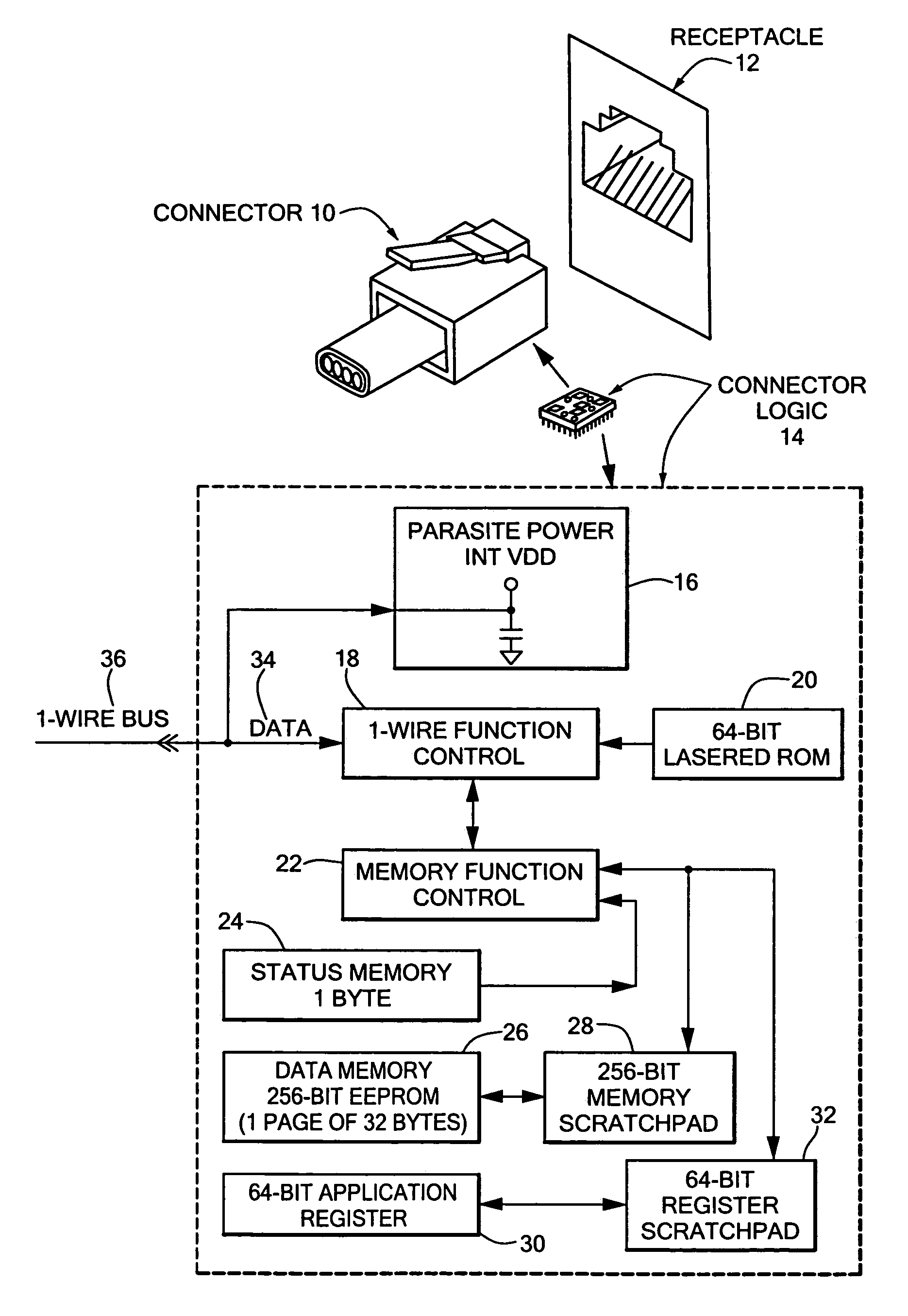
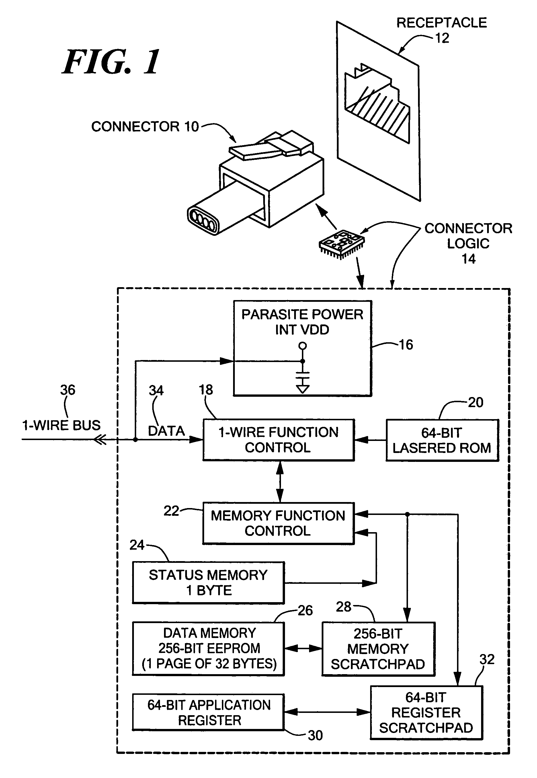
[0015]As shown in FIG. 1, an embodiment of the disclosed system includes a connector 10 for insertion into a receptacle 12. The connector 10 may, for example, consist of an eight pin modular jack, such as what is generally referred to as an RJ-45 connector, or other specific type of connector. Similarly, the receptacle 12 may consist of an 8 pin modular receptacle, or other suitable receptacle.

[0016]The connector 10 includes connector logic 14. One possible structure of the connector logic is illustrated in further detail by components 16, 18, 20, 22, 24, 26, 28, 30 and 32 in FIG. 1. The illustrative structure of the embodiment of the connector logic 14 of FIG. 1 may, for example, use a DS2430A 256-Bit 1-wire EEPROM, as provided by Dallas Semiconductor.

[0017]As shown in FIG. 1, the connector logic may include an internal power component operable to take power off of the same line that is used to convey data 34, such as digital data, and shown as the 1-wire bus 36 in FIG. 1. In an em...


PUM


Abstract

A system for connecting an I/O device to a central system including a cable connector having a memory for storing configuration information such as the type of the I/O device, characteristics of the I/O device, and/or the identity or characteristics of a user associated with the I/O device. Multiple universal slots are each capable of accepting the disclosed cable connector. When the disclosed connector is inserted into one of the slots, the central system operates to automatically detect the presence of the associated I/O device, and to read configuration information from the memory in the connector into memory within the central system. Configuration information read from the connector is used to configure the central system. The central system may use the configuration information from the connector memory to direct data and/or signals between the multiple universal slots and separate internal logic blocks associated with different types of I/O devices. User specific configuration information read by the central system from the connector memory may be used to configure user specific functions, such as, for example, speech recognition. The central system may further write various types of configuration information to the memory in the cable connector. Such information may include user specific characteristics determined during operation of the device, such as user specific speech characteristics.

Description

FIELD OF THE INVENTION[0001]The present invention relates generally to interconnecting input / output (I / O) devices to a central system, and more specifically to an intelligent cable design and interface system providing automatic device detection, identification, and system configuration.BACKGROUND OF THE INVENTION[0002]Many types of input / output (I / O) devices are connected to central systems through cables. In the case of an input device, the cable carries data from the device to the central system. For output devices, the cable passes data from the central system to the device. Additionally, cables may be used to convey data both to and from a central system in the case of cables for connecting transceiver devices. Various specific cable connector designs (sometimes referred to as “plugs”) exist for plugging cables into a central system. Specific cable connector designs are often incompatible with each other, requiring a central system to include different types of slots (sometimes...

Claims


Application Information

Patent Timeline
IPC IPC(8): G06F3/00G06F13/00
CPCG06F13/385
Inventor ROURKE, MICHAEL C.
Owner QUARTET TECH
Why Eureka
Try Eureka