
Circuit arrangement

a circuit arrangement and circuit technology, applied in the direction of fluid couplings, servomotor components, servomotors, etc., can solve the problem of particularly undesirable bypass arrangement, and achieve the effect of increasing pressur

Inactive Publication Date: 2008-09-23
HYDAC FLUITECHNIK GMBH
View PDF3 Cites 4 Cited by
  • Summary
  • Abstract
  • Description
  • Claims
  • Application Information

AI Technical Summary

Benefits of technology

[0008]An object of the present invention is to provide an improved circuit arrangement with a load sensing system, while maintaining known advantages, such that the consumers of the parallel section can be actuated independently of the pressure level of the consumers of the series section and such that higher pressures are available if they are required in the parallel section for the consumers therein.
[0010]In one preferred embodiment of the circuit arrangement of the present invention, the valve unit is formed from a hydraulically controllable proportional slide valve, preferably a 2-way proportional slide valve. Based on the proportional slide valve, it is possible to raise the pump pressure of the supply pump only to the extent necessary, providing the beneficial energy-saving operation of the overall system and thus the circuit arrangement.
[0011]In another preferred embodiment of the circuit arrangement of the present invention, between the supply pump and the return, a circulation manometric balance is connected to the supply circuit on which the highest load pressure altogether prevails. If a consumer is not active or required, the fluid (oil) with the low pressure loss can be returned via the circulation manometric balance to the tank, which in turn benefits an energy-saving operation.

Problems solved by technology

This bypass arrangement is especially undesirable when higher pressures are needed in the parallel section, for example, to be able to ensure operation of a machine and its parts.

Method used


Image

  • Circuit arrangement
  • Circuit arrangement

Examples


Embodiment Construction

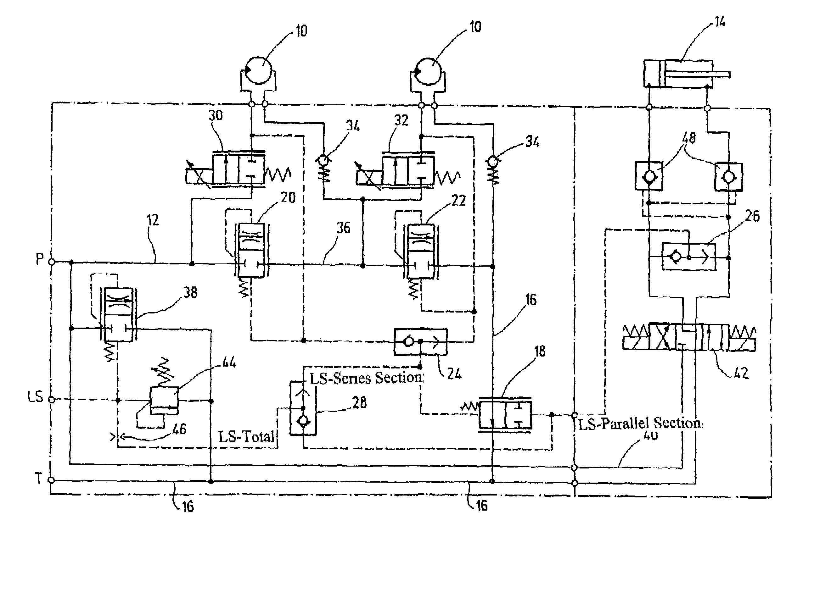
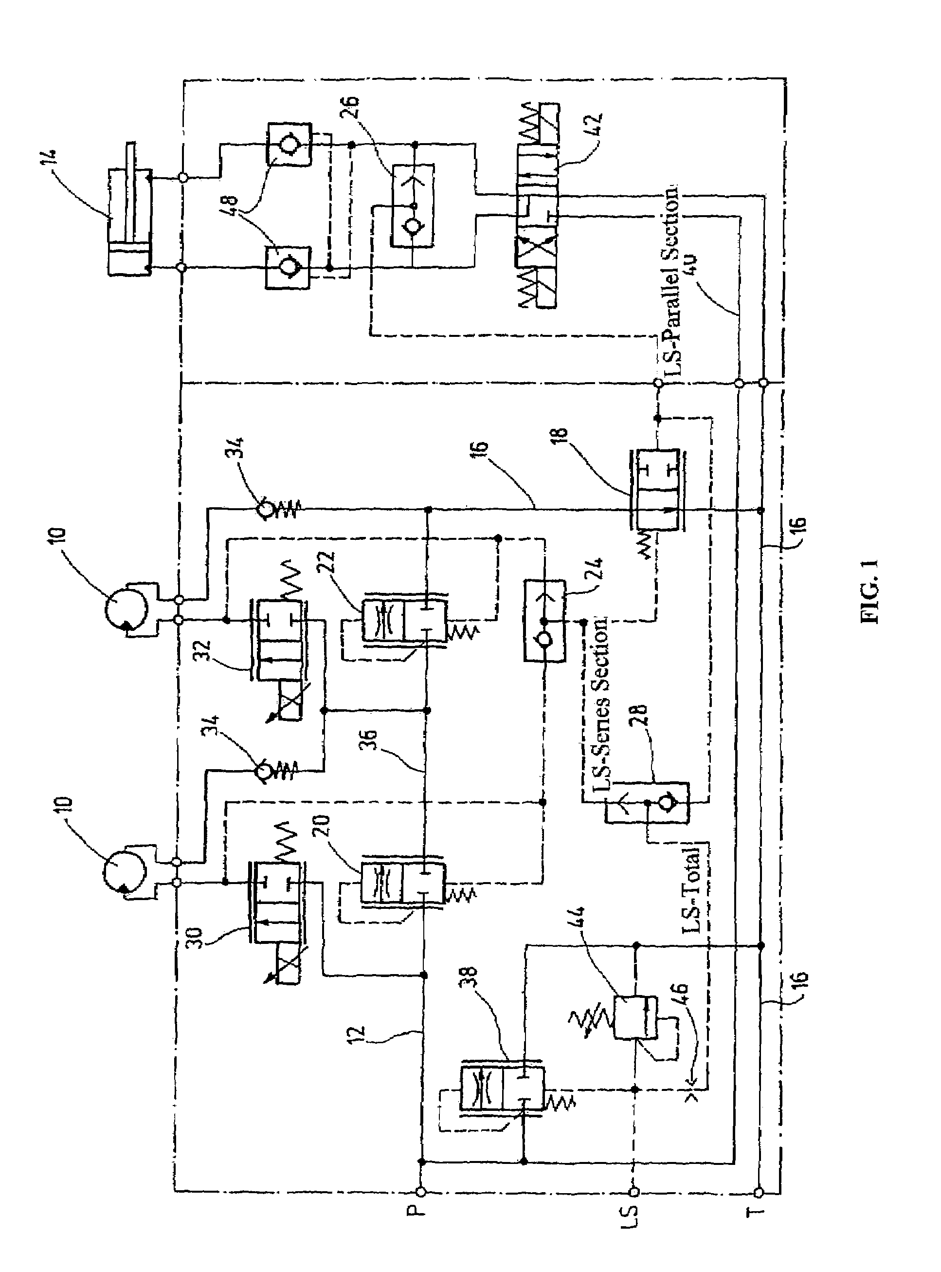
[0015]A circuit arrangement according to an embodiment of the present invention is equipped with a load sensing system labeled LS in the circuit diagram. The circuit arrangement is furthermore characterized in that individual consumers 10 are arranged in succession as series consumers of a series section in the direction of fluid flow. In addition to the series consumers 10 and parallel to them and with the formation of a parallel section, a parallel consumer 14 is connected to the hydraulic supply circuit 12. The series consumers 10 are individual hydraulic motors. The parallel consumer 14 is a conventional hydraulically operating working cylinder. The hydraulic supply circuit 12 discharges or is connected on its free ends into or to a supply pump P and into a tank T. The line of the supply circuit 12 connected to the tank T forms the return 16 of the circuit arrangement.

[0016]By the load sensing system LS, it is possible to determine the load pressure which is highest at the time ...


PUM


Abstract

A circuit arrangement includes a load sensing system (LS) with individual loads (10,14) arranged in series forming a series section, and in parallel forming a parallel section. A hydraulic supply circuit (12) includes a supply pump (P) and a runback (16) for fluid. The load sensing system (LS) determines the highest load pressure in the series section and the parallel section. The loads of the parallel section can be actuated independently from the pressure level of the loads of the series section due to the highest load pressure being transferred as a control pressure to a valve unit (18) such that, as long as the load pressure of the parallel section is higher than the load pressure of the series section, the valve unit restricts the runback (16) so that the pressure of the supply pump (P) matches or exceeds the pressure required in the parallel section. Sufficient fluid pressure for the load in the parallel section is ensured independently of the number of loads in the series section.

Description

FIELD OF THE INVENTION[0001]The present invention relates to a circuit arrangement with a load sensing system in which individual consumers arranged in series forming a series section and individual consumers arranged in parallel forming of a parallel section to one another are connected to a hydraulic supply circuit with at least one supply pump and a fluid return line. The load sensing system determines the highest load pressure at the time for the series section and the parallel section.BACKGROUND OF THE INVENTION[0002]A synonym for a load sensing system is the concept of a load pressure reporting system. The system is a hydraulic control system with pressure and volumetric flow matching, specifically to the instantaneous requirements of one or more consumers. Commercially common load sensing systems can be implemented both with a fixed displacement pump and with an adjustable displacement pump.[0003]In hydraulic systems and controls, the individual consumers can be arranged in s...

Claims


Application Information

Patent Timeline
Patent Type & Authority Patents(United States)
IPC IPC(8): F15B11/044F15B11/20F15B11/16
CPCF15B11/0445F15B11/20F15B11/162F15B2211/781F15B2211/30505F15B2211/3051F15B2211/30525F15B2211/3055F15B2211/327F15B2211/40515F15B2211/426F15B2211/455F15B2211/50518F15B2211/50536F15B2211/5151F15B2211/55F15B2211/575F15B2211/6055F15B2211/7053F15B2211/7058F15B2211/71
Inventor THIRY, GERD ANTONHOFFMANN, ALOISBAR, HARALD
Owner HYDAC FLUITECHNIK GMBH
Features
  • Generate Ideas
  • Intellectual Property
  • Life Sciences
  • Materials
  • Tech Scout
  • Unparalleled Data Quality
  • Higher Quality Content
  • 60% Fewer Hallucinations
Learn More