Leg assembly for home appliance

a technology for home appliances and legs, applied in the direction of machine supports, furniture parts, manufacturing tools, etc., can solve the problems of lowering the operation efficiency of workers, low productivity, and complex process for producing typical legs b>10/b>, so as to improve the efficiency of mounting and improve the structure. , the effect of improving the structur

Active Publication Date: 2008-09-23
LG ELECTRONICS INC
View PDF17 Cites 13 Cited by
  • Summary
  • Abstract
  • Description
  • Claims
  • Application Information

AI Technical Summary

Benefits of technology

[0010]An object of the present invention is to provide a leg assembly for electric home appliances with an improved structure for improving efficiency during mounting and productivity during manufacturing.
[0011]Another object of the present invention is to provide a leg assembly for electric home appliances with an improved structure for improving an external appearance so as to have a smooth and beautiful appearance.

Problems solved by technology

As aforementioned, the typical leg 10 has a problem of low productivity in order that a process for producing the typical leg 10 is very complex.
Therefore, the typical leg 10 has a problem of lowering operation efficiency of the worker.

Method used


Image

  • Leg assembly for home appliance
  • Leg assembly for home appliance
  • Leg assembly for home appliance

Examples


first embodiment

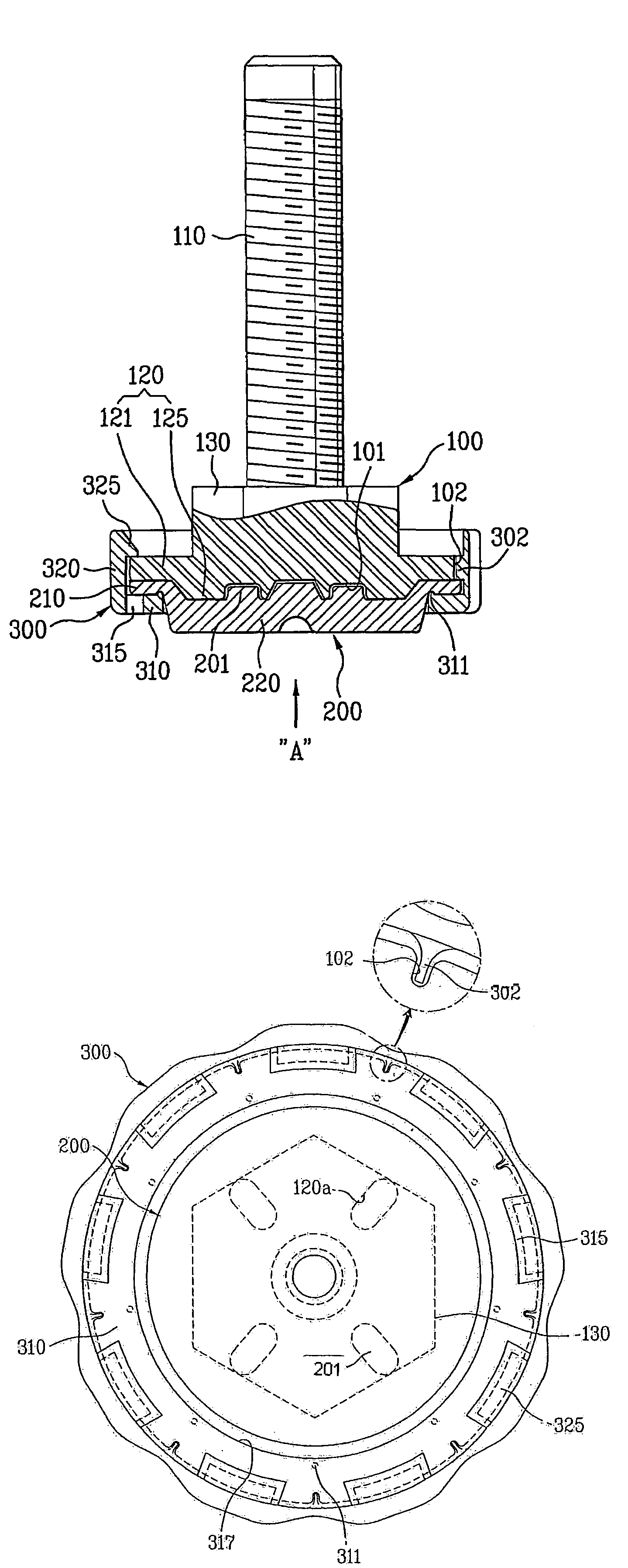
[0050]The leg bolt 100 is coupled to a home appliance (not shown) and includes a long screw 110 and a head 120 as illustrated in FIGS. 3, 5 and 6A.

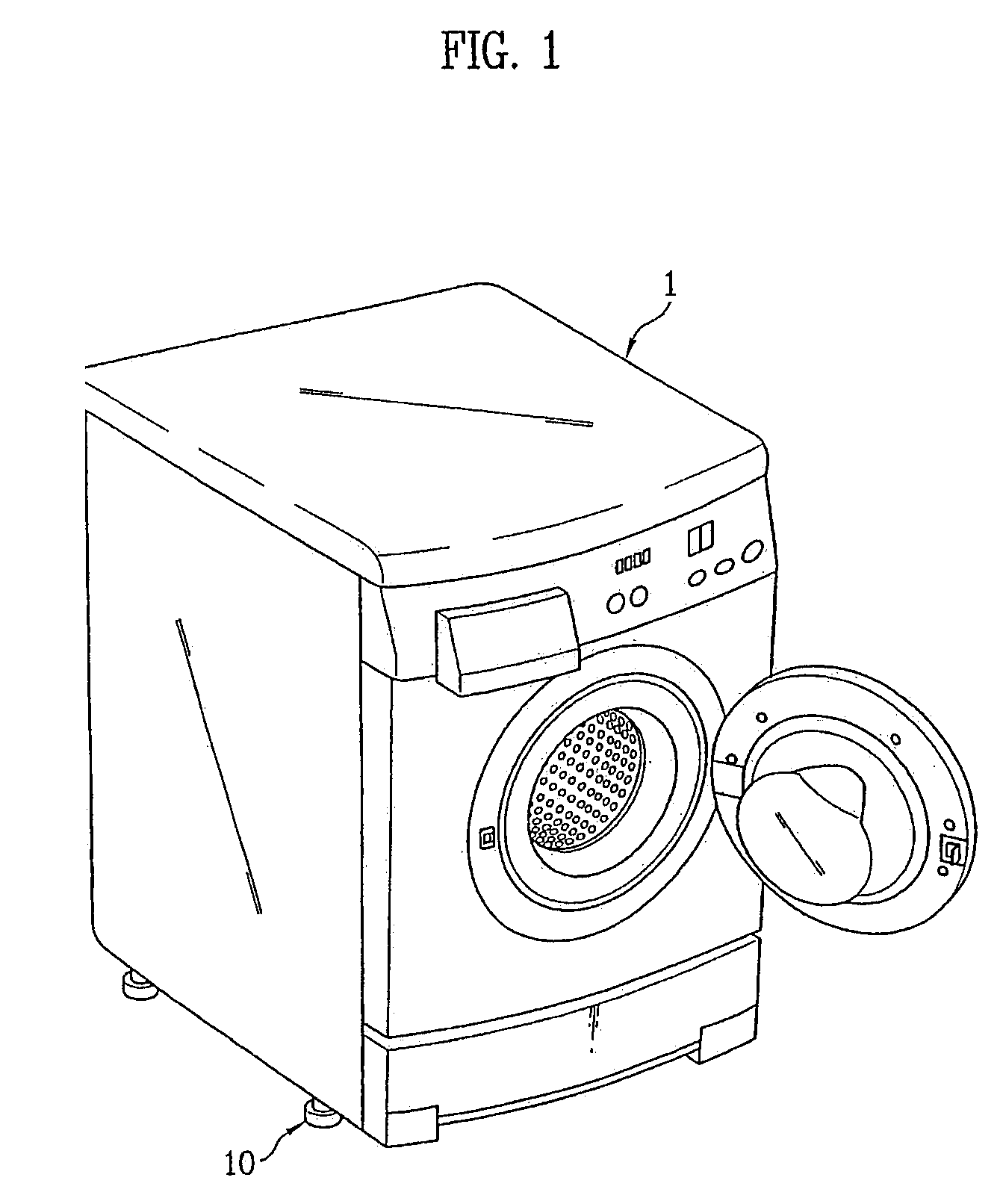
[0051]In this case, the screw 110 is coupled with a lower edge of the home appliance such that height of the leg bolt 100 is adjusted by rotating the screw 110.

[0052]The head 120 is provided at an end of the screw 110, and includes a flat head 121 and a platform 125. In this case, the flat head 121 is formed in a round plate form and the platform 125 is projected from the flat head 121 in an opposite direction of a forwarding direction of the screw 110.

[0053]Furthermore, an angled head 130 is further included between the head 120 and the screw 110. The angled head 130 is includes an angled outer circumference as illustrated in FIG. 6A. Therefore, when the angled head is provided, a worker can easily rotate the leg bolt 100 by using tools such as spanner or wrench.

[0054]Meanwhile, the pad 200 includes soft material, closely adhered to the ...

second embodiment

[0087]As illustrated in FIG. 7, the leg assembly in accordance with the second embodiment of the present invention includes a holder 300 having a leg bolt 100, a pad 200, and an inner holder 300a and an outer holder 300b. In this case, the structure of the leg bolt 100 and the pad 200 are same as illustrated in FIG. 6a and FIG.6b. However, the structure of the leg bolt 100 and the pad 200 illustrated in FIGS. 6a and 6b is described enough in the description of the first embodiment of the present invention.

[0088]Therefore, the description of the leg bolt 100 and the pad will be omitted, and hereinafter, the holder 300 including the inner holder 300a and the outer holder 300b will only be described. As a reference, same reference numbers used in the first embodiment of the present invention will be used for the leg bolt 100 and the pad 200.

[0089]Contrary to the holder including one piece in the first embodiment, the holder 300 in accordance with the second embodiment includes two sect...


PUM


Abstract

Disclosed is a leg assembly for electric home appliances for supporting an electric home appliance such as a washing machine and a clothes dryer. The leg assembly in accordance with the present invention includes, a leg bolt (100) having a screw (110) coupled with the electric home appliance and a head (120) provided at an end of a screw (110) a pad made of a soft material and closely adhered to the head (120) an being in contact with a floor; and at least one holder (300) being coupled with the head (120) for fixing the head (120) and the pad (200) by pressing the pad (200) toward the head (120).

Description

TECHNICAL FIELD[0001]The present invention relates to a leg assembly for electric home appliances, and more particularly, to a leg assembly for supporting electric home appliances such as a washing machine and a clothes dryer.BACKGROUND ART[0002]Legs for electric home appliances are generally provided at corners of electric home appliances for supporting the appliance. In general, installation condition largely influences to lifetime and reliability of the appliance such as a washing machine, a clothes dryer, a refrigerator, and a dish washer. The legs applied to the electric home appliances are formed in a screw structure for easily controlling height of each home appliance.[0003]In FIGS. 1 and 2 illustrate an example showing a leg 10 formed in a screw form is applied to a drum washing machine. Hereinafter, the structure of the leg 10 will be described referring to the drawings.[0004]Referring to FIG. 2, a traditional leg 10 includes a pad 15 covering a long screw 11a and a leg bol...

Claims


Application Information

Patent Timeline
Patent Type & Authority Patents(United States)
IPC IPC(8): F16M11/00A47B91/02D06F39/12F16M7/00
CPCA47B91/024F16M7/00D06F39/125Y10T16/209
Inventor CHA, WOONG KILKIM, BO YON
Owner LG ELECTRONICS INC
Why Eureka
Try Eureka