Winding structure for efficient switch-mode power converters

a winding structure and switch-mode technology, applied in the direction of transformer/inductance details, basic electric elements, coils, etc., can solve the problems of limiting the uniform current and eddy current that may circulate in the winding, and the uniform winding impedance, so as to reduce the loss of eddy current, improve the efficiency of the converter and the core utilization, and improve the uniformity of current.

Active Publication Date: 2008-09-23
MYPAQ HLDG LTD
View PDF137 Cites 53 Cited by
  • Summary
  • Abstract
  • Description
  • Claims
  • Application Information

AI Technical Summary

Benefits of technology

[0010]The present invention provides a winding structure for planar magnetics used in switched-mode power converters that improves converter efficiency and core utilization by reducing eddy current losses and improving the uniformity of the current in the secondary windings.
[0011]This is accomplished by forming “cutout” and / or “keep away” regions in the windings around the outer or center legs to keep both the AC and DC winding resistances low. The keep away regions are formed at the exterior edge of the winding nearest the center leg and serve to space the winding further away from the strongest leakage fields or fringing field. The cutouts are formed in the interior of the winding and serve to form an “island” in the winding that disrupts the induced eddy currents in the presence of moderate fields. The cutouts and keep away regions need only be formed on the portions of the windings near the center leg and in the windings nearest the air gap.
[0012]The air gap creates a fringing field whose strength decreases as it moves down and away from the air gap. Consequently when a plurality of windings are formed on the multiple layers of a printed circuit board, any of the windings that lie within a first multiple of a length of the air gap measured from the plate are formed with both an interior cutout and an exterior keep away region. Any of the windings that lie between the first multiple and a second multiple are formed with only an interior cutout. Finally, any remaining windings that lie outside the second multiple have neither interior cutouts nor exterior keep away regions. Typical values for the first and second multiples are five and ten, respectively. By configuring the stack of windings in this manner, the net AC and DC winding resistance remain low, losses due to eddy currents are minimized and the current through the windings is approximately uniform. As a result, the different windings are shielded from the deleterious effects of the fringing field.

Problems solved by technology

Transformers and inductors used within these power converters may be large and bulky and often limit their efficiency, power density and reliability.
The AC resistance is a function of skin depth at a given frequency and magnetic field impinging on the windings, which leads to non-uniform currents and eddy currents that may circulate in the windings.
Some of the windings layers will inevitably be close to the air gap 32 where the strong fringing flux surrounding the air gap will induce eddy currents in the windings and also lead to non-uniform winding impedance.
This in turn increases total winding losses and lowers converter efficiency.
These losses reduce the efficiency of the power converter.
Furthermore, because the current in the windings closer to the air gap is attracted towards the high field, the currents flowing through them and consequent losses are highly non-uniform.

Method used


Image

  • Winding structure for efficient switch-mode power converters
  • Winding structure for efficient switch-mode power converters
  • Winding structure for efficient switch-mode power converters

Examples


Embodiment Construction

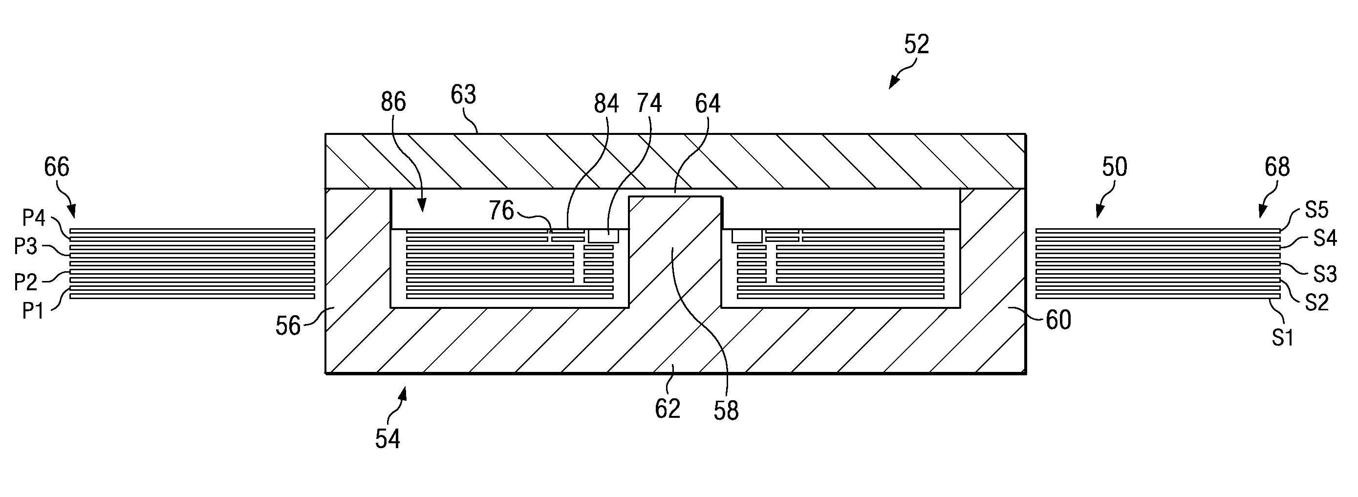
[0021]The present invention modifies the conventional winding structure for planar integrated magnetics by etching cutout and / or keep away regions in the planar copper windings near the center leg. By accepting a marginal increase in the DC winding resistance, we are able to drastically reduce the AC winding resistance and the eddy current losses in the presence of a leakage field by at least 25%. The net result is improved current uniformity with lower losses, hence higher converter efficiency. Because the strength of the fringing flux decreases as you move down and away from the air gap, windings closest to the air gap are formed with both keep away regions and cutouts. Windings a little further away are formed with only cutouts and the windings furthest away are unchanged. The precise configuration is determined by the core structure, air gap and winding arrangements to optimize converter efficiency.

[0022]By way of example, the improved winding arrangement was implemented and com...


PUM

PropertyMeasurementUnit
widthaaaaaaaaaa
widthaaaaaaaaaa
widthaaaaaaaaaa

Abstract

Cutout and / or keep away regions are etched in the winding structure near the gapped center leg of a magnetic core. This reduces eddy current losses caused by the leakage field and improves current uniformity and current sharing between windings thereby increasing converter efficiency. Windings closest to the air gap are suitably formed with both keep away regions and cutouts. Windings a little further away are formed with only cutouts, and the windings furthest away are unchanged. This approach keeps the net winding losses low in the presence of a fringing field. The precise configuration is determined by the core structure, air gap and winding arrangements.

Description

BACKGROUND OF THE INVENTION[0001]1. Field of the Invention[0002]This invention relates to switched-mode power converters and more specifically to an improved winding structure for the magnetic core that reduces eddy currents.[0003]2. Description of the Related Art[0004]Power converters are key components in many military and commercial systems and often govern size and performance. Power density, efficiency and reliability are key characteristics used to evaluate the characteristics of power converters. Transformers and inductors used within these power converters may be large and bulky and often limit their efficiency, power density and reliability. These deficiencies can be improved by using a high-frequency “switch-mode” architecture instead of traditional step-down configuration and by replacing conventional core-and-coil designs with “planar integrated magnetics.”[0005]Planar integrated magnetics offer several advantages, especially for low-power dc-dc converter applications, s...

Claims


Application Information

Patent Timeline
Patent Type & Authority Patents(United States)
IPC IPC(8): H01F5/00
CPCH01F27/2804H02M3/28H01F2027/2819H01F27/34
Inventor MEHROTRA, VIVEKSUN, JIAN
Owner MYPAQ HLDG LTD
Why Eureka
Try Eureka