Apparatus for changing the attack angle of a cavitator on a supercavatating underwater research model

a technology of cavitator and attack angle, which is applied in the direction of instruments, vessel construction, transportation and packaging, etc., can solve the problems of assembly not being suitable for use with supercavitating underwater research models, time-consuming and laborious, and no prior art patent discloses an apparatus

Inactive Publication Date: 2008-09-30
THE UNITED STATES OF AMERICA AS REPRESENTED BY THE SECRETARY OF THE NAVY
View PDF21 Cites 28 Cited by
  • Summary
  • Abstract
  • Description
  • Claims
  • Application Information

AI Technical Summary

Benefits of technology

[0007]It is therefore an object of the present invention to provide an apparatus that can efficiently, quickly and accurately vary the angle of attack of a supercavitating underwater research model while the research model is in motion.
[0008]It is another object of the present invention to provide an apparatus that can vary the angle of attack of a supercavitating underwater research model that is inexpensive to manufacture and implement.
[0009]It is a further object of the present invention to provide an apparatus that can vary the angle of attack of a supercavitating underwater research model from a remote location.
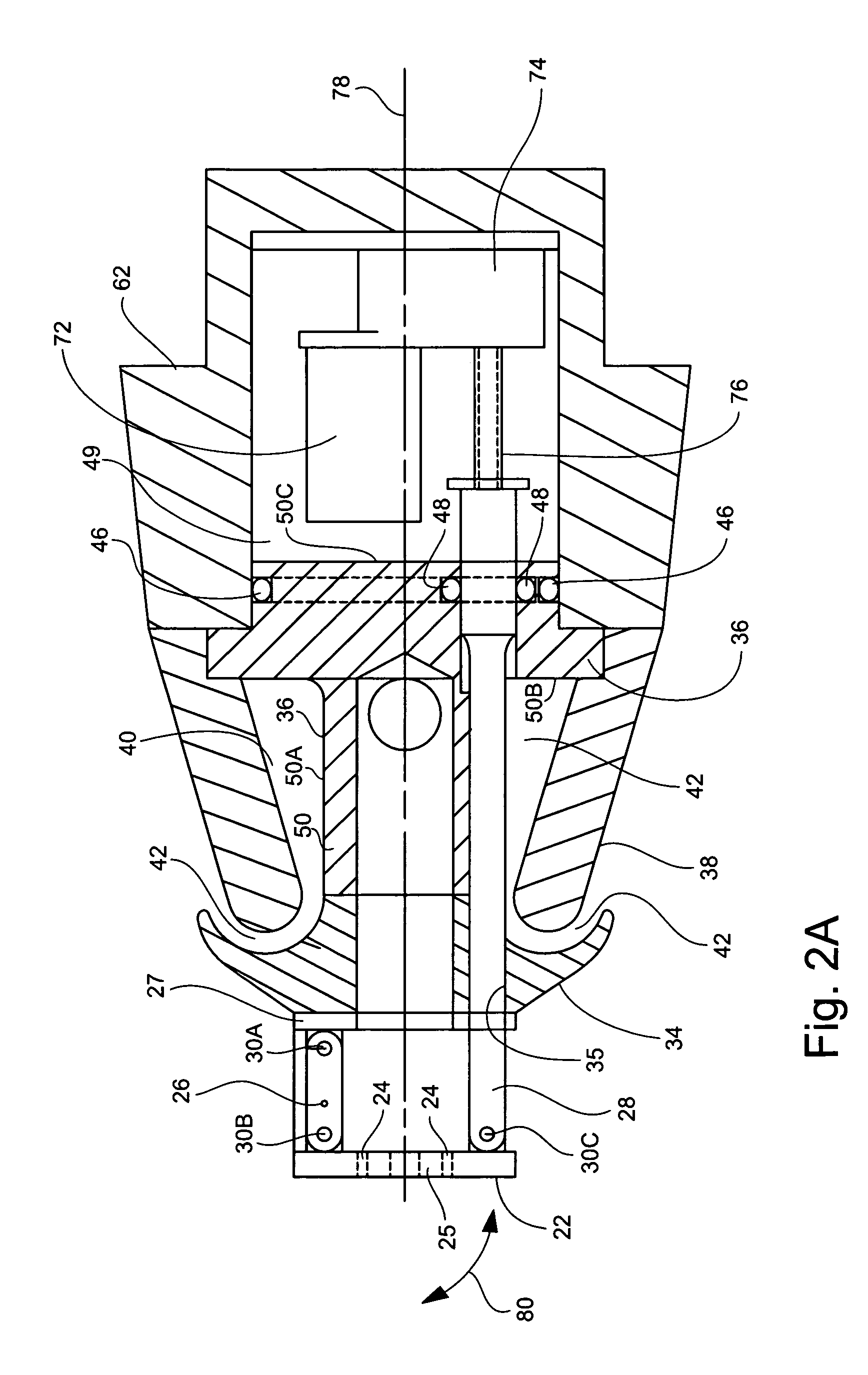
[0012]In one aspect, the present invention is directed to an apparatus for changing the angle of attack of a cavitator on a supercavitating underwater research model. The apparatus generally comprises a nose assembly having a pivotable cavitator tilt plate and a watertight compartment, an actuator member that is supported by the nose assembly and has a first distal end movably attached to the cavitator tilt plate and a second distal end opposite the first distal end and located within the watertight compartment, and a drive system positioned in the watertight compartment for axially moving the actuator member in a first direction and in a second direction that is opposite the first direction. The drive system has inputs for receiving electrical power signals that control the drive system to move the actuator member in a desired direction. The apparatus further comprises an electrical power system positioned at a remote location for providing the electrical power signals to the drive system when the supercavitating underwater research model is either at standstill or in motion. Thus, the apparatus of the present invention allows the angle of attack of the cavitator to be changed even when the tow tank is filled with water and the supercavitating underwater research model is submerged therein.

Problems solved by technology

However, this is a time consuming endeavor because a significant amount of time is needed to fill and drain the tow tank.
The prior art discloses several moveable nose assemblies, however, such assemblies are not suitable for use with supercavitating underwater research models.
None of these prior art patents disclose an apparatus that addresses the aforementioned problem of changing the angle of attack of a supercavitating underwater research model while such model is in motion and underwater.

Method used


Image

  • Apparatus for changing the attack angle of a cavitator on a supercavatating underwater research model
  • Apparatus for changing the attack angle of a cavitator on a supercavatating underwater research model
  • Apparatus for changing the attack angle of a cavitator on a supercavatating underwater research model

Examples


Embodiment Construction

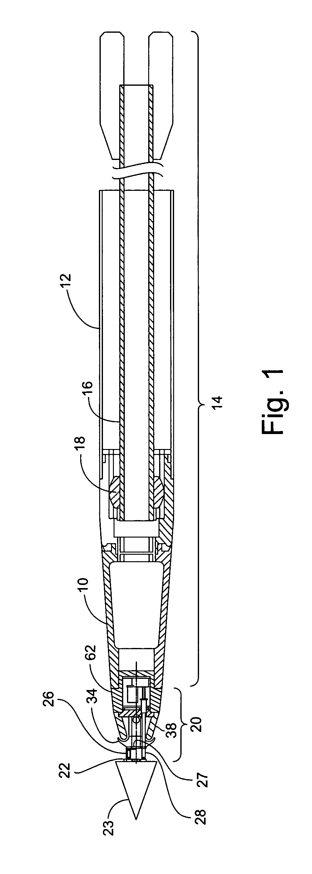
[0023]Although the apparatus of the present invention is configured to be used with a super cavitating underwater research model, the ensuing description is in terms of the supercavitating underwater research model being simulated by other components and structures. Referring to FIG. 1, the supercavitating underwater research model is simulated by forward shell 10 and aft shell 12. Forward shell 10 is connected to aft shell 12 to form a simulated super-cavitating underwater research model 14 (hereinafter “model 14”). Model 14 is supported by sting 16. Aft shell 12 covers sting 16 to simulate the length an actual super-cavitating underwater research model. Sting 16 is attached to model 14 by a ball joint assembly 18. The other end of sting 16 is fastened to a strut (not shown). The apparatus of the present invention comprises nose assembly 20 which is sized to partially fit in forward shell 10.

[0024]Referring to FIGS. 1, 2A, 2B and 2C, there is shown a cross-sectional view of nose as...


PUM


Abstract

An apparatus for changing the angle of attack of a cavitator on a supercavitating underwater research model. The apparatus has a nose assembly that has a pivotable cavitator tilt plate, an actuator member and a drive system engaged with the actuator member to drive the actuator member so as to tilt the cavitator tilt plate to a desired angle. Power components are remotely located and accessible to an operator so as to enable an operator to vary the angle of the cavitator tilt plate while the supercavitating underwater research model is underwater and in motion.

Description

STATEMENT OF GOVERNMENT INTEREST[0001]The invention described herein may be manufactured and used by or for the Government of the United States of America for governmental purposes without the payment of any royalties thereon or therefor.BACKGROUND OF THE INVENTION[0002]1. Field of the Invention[0003]The present invention generally relates to an apparatus for changing the attack of a cavitator on a supercavitating underwater research model.[0004]2. Description of the Prior Art[0005]Supercavitating underwater vehicles and projectiles are known in the art. One such supercavitating underwater projectile is described in Harkins et al., U.S. Pat. No. 5,955,698. This projectile uses a supercavitating nose section that provides a cavitation bubble of sufficient size to encompass the body of the projectile which reduces hydrodynamic drag. The cavitating nose section described in the Harkins et al. is a fixed position cavitating nose section and cannot be maneuvered so as to vary the angle o...

Claims


Application Information

Patent Timeline
Patent Type & Authority Patents(United States)
IPC IPC(8): F42B15/20
CPCB63B1/32B63B9/02F42B19/005F42B10/42Y02T70/12B63B71/20Y02T70/10
Inventor NEDDERMAN, WILLIAM H.
Owner THE UNITED STATES OF AMERICA AS REPRESENTED BY THE SECRETARY OF THE NAVY
Why Eureka
Try Eureka