Parallel-guiding mechanism for compact weighing system

a guiding mechanism and compact technology, applied in the field of weighing modules, can solve the problems of limiting the thickness of thin flexure joints, weighing cells based on electromagnetic force compensation, and weighing cells based on strain gauge principles, so as to increase the bending stiffness of a very thin stationary parallel leg and increase the bending stiffness of the sheet metal part. , the effect of increasing the bending stiffness

Active Publication Date: 2008-09-30
METTLER TOLEDO AG
View PDF25 Cites 30 Cited by
  • Summary
  • Abstract
  • Description
  • Claims
  • Application Information

AI Technical Summary

Benefits of technology

[0030]Flat parallel-guiding diaphragms can be perforated by spiral-shaped or concentric cuts perpendicular to the diaphragm plane. Parallel-guiding diaphragms with concentric perforations have ring-shaped spring segments which for each perforation need to have at least one material connection from one segment to another or to the stationary parallel leg or the movable parallel leg. These material connections can be arranged at locations that are offset from each other in order to minimize the stiffness of the parallel-guiding diaphragm. If parallel-guiding diaphragms with spiral-shaped concentric perforations are elastically deflected in or against the load direction so that the movable parallel leg lies in a plane orthogonal to the load direction which has a parallel offset from the plane of the stationary parallel leg, the spiraling or concentric perforated pattern of the parallel-guiding members can take a cone shape.
[0032]With all parallel-guiding mechanisms that have a meander-like configuration of the parallel-guiding members, or with all parallel-guiding mechanisms that have parallel-guiding diaphragms, particular attention needs to be given to the fact that in arrangements with a plurality of upper parallel-guiding members and a plurality of lower parallel-guiding members extending between the stationary parallel leg and the movable parallel leg, there needs to be symmetry between the parallel-guiding members so that the displacement of the movable parallel leg can only take place in or against the direction of the load and the movable parallel leg will not become tilted out of the load direction as a result of asymmetrically distributed forces acting between the individual upper and / or individual lower parallel-guiding members.
[0034]For achieving precise measuring results with an exemplary weighing cell, the form stability of the stationary parallel leg and its support and fixation on the weighing cell can be taken into consideration. An exemplary stationary parallel leg can have the same outside contour as the weighing cell housing. It can be advantageous if the stationary parallel leg is structured as a closed frame with the parallel-guiding members arranged at the inside of the frame. Furthermore, the bending stiffness of a very thin stationary parallel leg can be markedly increased by rolled or folded contour borders as well as by press-formed stiffening beads. The rolling of contour borders is a process where a thin sheet metal part is rolled in at the edge, a technique that is used for example in the production of sheet metal cans. Folding a contour border in the context of the present disclosure refers to a border portion that is folded to stand up at an angle from the surface plane of a sheet metal part, so that the resulting angle profile in the border area increases the bending stiffness of the sheet metal part. However, a comparable border area can also be produced for example by milling. The same can be said for producing projecting ribs instead of impressed beads. With the foregoing concepts, the stationary parallel leg can be supported over a large area, is not deformed by a load acting on the device, and the connecting elements that could cause internal stresses in the material can be arranged as far away as possible from the flexibly bending parallel-guiding members or from the thin flexure joints. The movable parallel leg can of course likewise be given an increased bending stiffness over all or part of its length by means of stiffening beads or ribs.

Problems solved by technology

However, strain-gauge-based weighing cells—in contrast to weighing cells based on the principle of electromagnetic force compensation—may not suitable for applications involving the determination of a mass in the range of micrograms to grams.
The parallel-guiding mechanisms disclosed in the state-of-the-art references have a disadvantage that the maximally tolerable stress in the material being used imposes a limit on reducing the thickness of the thin flexure joints and that the parallel-guiding mechanism becomes very sensitive to overloads if the flexure joints or the elastic parallel-guiding members are made thinner.
However, this can lead to unfavorable dimensions for weighing modules that are to be used in a device for weighing uniform weighing objects, so that the devices become expensive, voluminous and complicated.

Method used


Image

  • Parallel-guiding mechanism for compact weighing system
  • Parallel-guiding mechanism for compact weighing system
  • Parallel-guiding mechanism for compact weighing system

Examples


Embodiment Construction

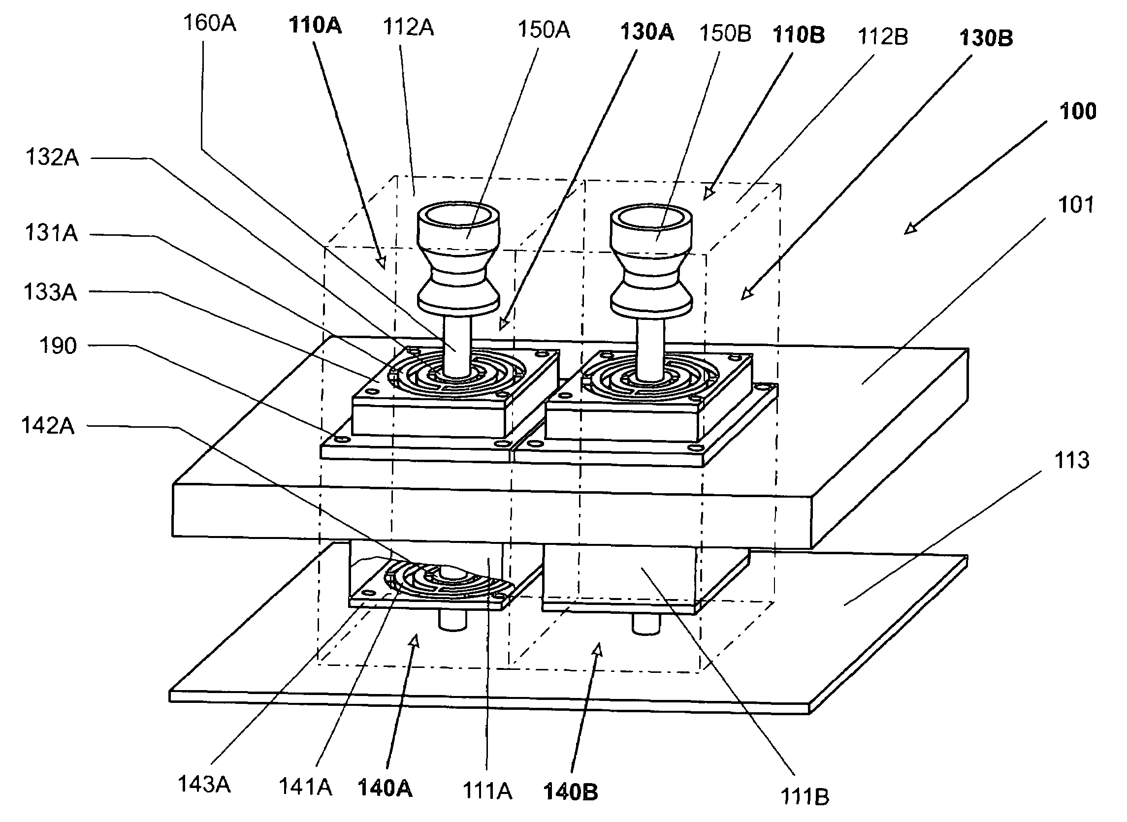
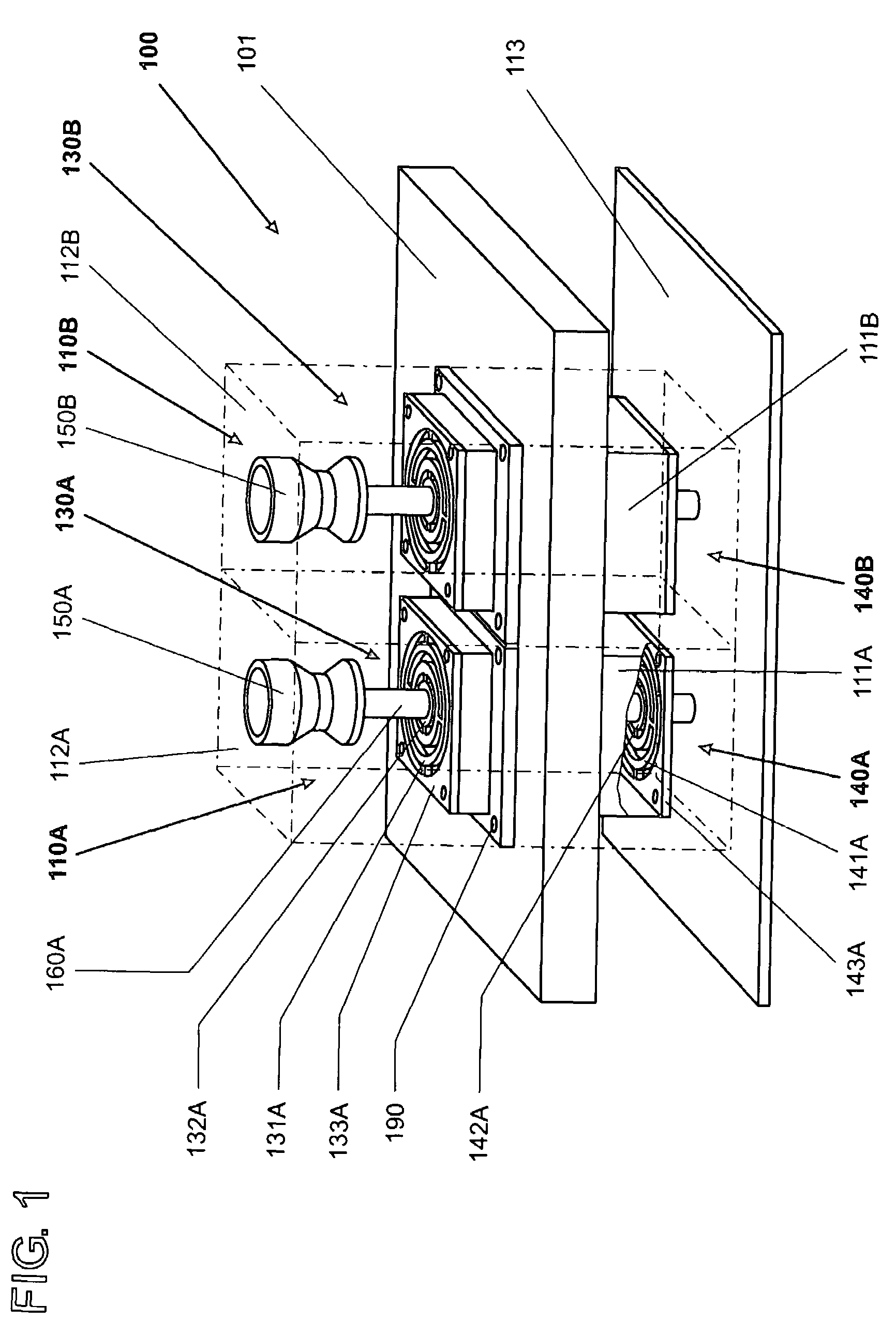
[0058]In the perspective representation of FIG. 1, an exemplary receiving structure 101 is shown with two weighing modules 110A, 110B, together constituting an exemplary device 100 for the weighing of substantially uniform objects. Each of the weighing modules 110A, 110B has a weighing cell 111A, 111B with a load receiver 150A, 150B. Each of the weighing modules 110A, 110B is arranged within a design space 112A, 112B. Each dimension of a design space in the plane that extends orthogonal to the load direction is delimited by the design spaces occupied by the neighboring weighing cells or represents the largest dimension of the weighing cell 111A, 111B in said plane within the respective design space 112A, 112B. The dimension in the load direction is delimited for example by a housing floor 113 that is solidly connected to the receiving structure. The limits of the design spaces 112A, 112B against the load direction are formed, e.g., by the upper rims of the load receivers 150A, 150B,...


PUM


Abstract

An exemplary weighing module is disclosed which has a load receiver and a weighing cell that are connected to each other by a force-transmitting rod, wherein the weighing module is arranged inside a design space whose dimensions in a plane extending orthogonal to the load direction are limited by the design spaces occupied by neighboring weighing cells or represent the largest dimension of the weighing cell in said plane. An exemplary weighing cell has a parallel-guiding mechanism in which at least one movable parallel leg which is connected to the force-transmitting rod and at least one stationary parallel leg are arranged with a predefined guiding distance from each other, connected to each other by at least one upper parallel-guiding member and at least one lower parallel-guiding member. The effective length of the parallel-guiding members is larger than the guiding distance, and the movable parallel leg does not protrude out of the design space.

Description

RELATED APPLICATIONS[0001]The present application claims priority under 35 U.S.C. §119 to European Application No. 05104522.7 filed May 26, 2005, the contents of which are hereby incorporated by reference in their entirety.BACKGROUND[0002]1. Field[0003]A weighing module, and a device that is used to weigh substantially uniform weighing objects with a given number of weighing modules, are disclosed. Each module has a load receiver that is connected to a weighing cell through a force-transmitting rod. A parallel-guiding mechanism is associated with each force-transmitting rod to constrain the latter in a parallel-guided movement in the direction of the load.[0004]Applications for a device designed to weigh substantially uniform weighing objects are found in automated production- and testing systems where balances of a modular configuration—so-called weighing modules—are particularly well suited to be integrally incorporated into these systems. In essence, the balances used for this pu...

Claims


Application Information

Patent Timeline
Patent Type & Authority Patents(United States)
IPC IPC(8): G01G9/00G01G21/00
CPCG01G21/244
Inventor GENOUD, DOMINIQUEBURKHARD, HANS-RUDOLFEMERY, JEAN-CHRISTOPHE
Owner METTLER TOLEDO AG
Why Eureka
Try Eureka