Fuel injectin valve

A fuel injection valve and fuel supply technology, which is applied to fuel injection pumps, fuel injection devices, special fuel injection devices, etc., can solve problems such as damage to internal combustion engines, and achieve the effect of reducing manufacturing costs.

Inactive Publication Date: 2003-07-16
ROBERT BOSCH GMBH
View PDF2 Cites 0 Cited by
  • Summary
  • Abstract
  • Description
  • Claims
  • Application Information

AI Technical Summary

Problems solved by technology

With such fuel injection valves, there is the danger that in the event of a fault, for example, a continuous injection of fuel through the fuel injection valve occurs during the control of the pressure chamber pressure, which can lead to damage to the associated internal combustion engine

Method used


Image

  • Fuel injectin valve
  • Fuel injectin valve
  • Fuel injectin valve

Examples


Embodiment Construction

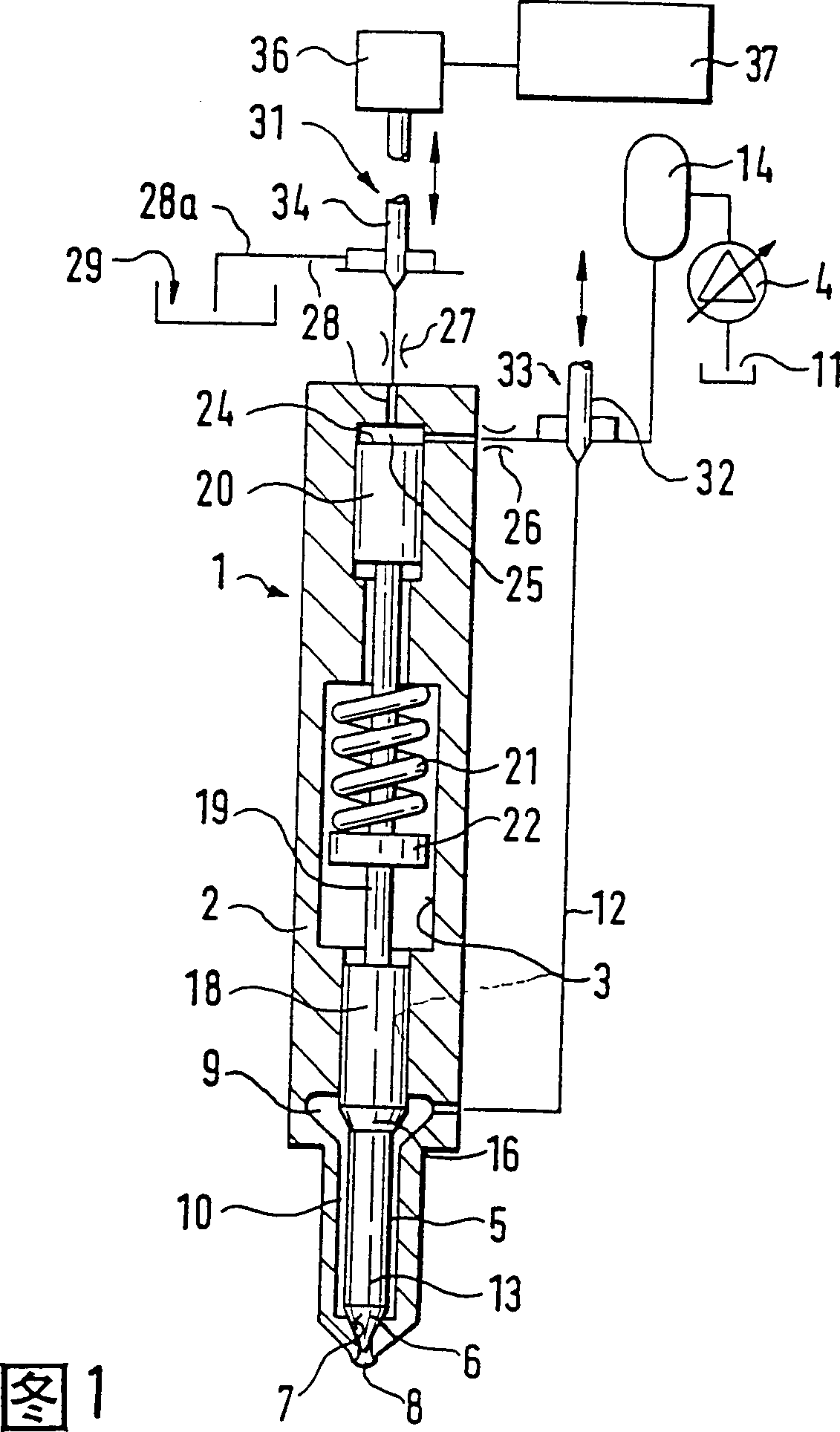
[0016] FIG. 1 shows a simple view of an injection valve 1 having an injection valve housing 2 with a bore 3 in which an injection valve element 5 is guided, which The fuel injection valve element 5 has a conical sealing surface 6 at one end, which cooperates with a conical valve seat 7 at the end of the bore. Downstream of the valve seat 7 are arranged oil injection openings 8 which are separated from a pressure chamber 9 when the sealing surface 6 is on the valve seat 7 . The pressure chamber 9 extends on an annular space 10 around the part 13 of the fuel injection valve element having a smaller diameter upstream of the sealing surface 6 as far as the valve seat 7 . The pressure chamber 9 can communicate via a pressure line 12 with a high-pressure oil source in the form of a high-pressure oil reservoir 14, which is placed at the injection pressure from the oil reservoir 11 by, for example, a high-pressure oil delivery pump 4 with a variable fuel delivery ratio. The lower fue...


PUM


Abstract

A fuel injection valve for an internal combustion engines is proposed, in which the control of the fuel injection valve member is controlled through the control of the pressure of a control chamber (25). This chamber is either relieved by means of a control valve (31) or is subjected to a high pressure, which brings the fuel injection valve member into the closed position. At the same time as the relief of the control chamber, a valve member (33) of a safety valve that controls the fuel supply to the fuel injection valve is opened so that upon opening of the fuel injection valve, high-pressure fuel simultaneously also can travel by way of a pressure line (12) from a high-pressure fuel reservoir (14) to the injection openings (8) of the fuel injection valve (1). After the end of the injection, the valve member (33) is closed again, together with the closing of the fuel injection valve member (5). Consequently, in the event of a malfunction, unwanted fuel is prevented from reaching injection for a long period of time and consequently possibly destroying the associated engine due to overdosing.

Description

technical field [0001] The invention relates to a fuel injection valve. Background technique [0002] In a fuel injection valve of this type known from GB-PS 1 320 057, only the relief of the control chamber is controlled by the control valve. The pressure chamber is always in communication with the high pressure reservoir. With such fuel injection valves, there is the danger that in the event of a fault, for example, a continuous injection of fuel through the fuel injection valve occurs during the control of the pressure chamber pressure, which can lead to damage to the associated internal combustion engine . Contents of the invention [0003] According to the invention, a fuel injection valve for an internal combustion engine is proposed, which has a high-pressure oil reservoir fed by a high-pressure pump, which is connected to a pressure chamber via a pressure line, the pressure line The passage is controlled by a valve element of a valve by which the connection to t...

Claims


Application Information

Patent Timeline
Patent Type & Authority Patents(China)
IPC IPC(8): F02M47/00F02M47/02F02M51/00F02M51/06F02M59/46F02M63/00
CPCF02M2200/502F02M47/027F02M2200/701F02M63/0061F02M47/02F02M63/0026
Inventor 鲁道夫·海因茨弗里德里希·伯金
Owner ROBERT BOSCH GMBH
Why Eureka
Try Eureka