Unlock instant, AI-driven research and patent intelligence for your innovation.

Object velocity measuring apparatus and object velocity measuring method

a technology of object velocity and measuring apparatus, applied in the direction of traffic control system, devices using optical means, instruments, etc., can solve the problems of difficulty in detecting the area where the object moves, limited velocity measurement accuracy to blocks (pixels) at best, and the component of the object in the image decreases, so as to achieve high accuracy

Active Publication Date: 2008-09-30
KK TOSHIBA
View PDF9 Cites 3 Cited by
  • Summary
  • Abstract
  • Description
  • Claims
  • Application Information

AI Technical Summary

Benefits of technology

This approach improves velocity measurement accuracy by calculating center-of-gravity position coordinates with pixel-level precision, allowing for robust object velocity measurement immune to noise and disturbances, and effectively handling small objects and varying environments.

Problems solved by technology

With the first approach, however, when the size of the object in the image is small, it is difficult to sense the area where the object moves.
Furthermore, since the first approach is based on block matching, the velocity measuring accuracy is limited to blocks (that is, pixels) at best.
On the other hand, since the surroundings of the imaging device vary severely outdoors, the signal component of the object in the image decreases or the noise component increases, which can prevent the object from being sensed temporarily.
In this case, it is difficult to correlate the object positions between the frames.
In this case, it is difficult to correlate segments between a plurality of frames.
Under such circumstances, the second approach is particularly unsuitable for measuring the object velocity outdoors.

Method used


Image

  • Object velocity measuring apparatus and object velocity measuring method
  • Object velocity measuring apparatus and object velocity measuring method
  • Object velocity measuring apparatus and object velocity measuring method

Examples


Embodiment Construction

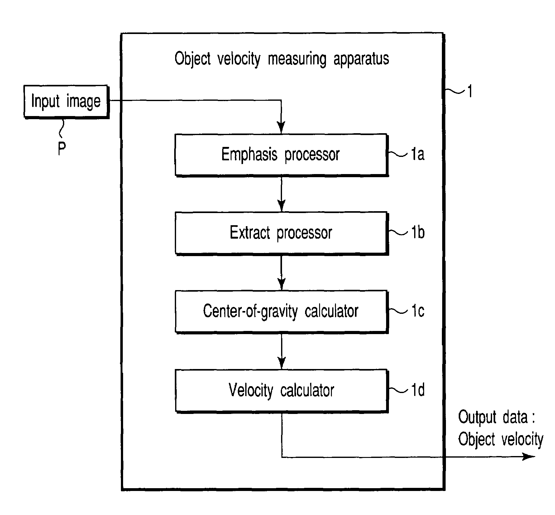
[0020]FIG. 1 is a view showing an embodiment of a system to which an object velocity measuring apparatus according to the present invention is applied. In the system, a video camera 200 installed in an airplane 100 photographs vehicles running on the road. The video camera 200 outputs images successive in time. After a noticeable object is set in each image, the moving velocity of the object in the photographic field is determined. On the basis of the moving velocity of the object and the altitude (or photographic altitude) of the airplane 100, the running velocity of a vehicle on the road can be calculated. The calculated velocity corresponds to the relative velocity between the airplane 100 and the vehicle. When the flying velocity of the airplane 100 is known, the moving velocity (or running velocity) of a movable body can be calculated. The object velocity measuring apparatus related to the present invention is used to calculate the moving velocity of the object in the photograp...


PUM


Abstract

An object velocity measuring apparatus of this invention for measuring an object velocity in a photographic field from a plurality of photographic frames made up of a plurality of pixels comprises an object area extracting unit configured to extract, as an object area, a set of pixels from which an object has been sensed over at least M (M<N) of N successive frames including the present frame, a center-of-gravity computing unit configured to calculate the center-of-gravity position coordinates of the extracted object area in the photographic field, and a velocity computing unit configured to calculate the object velocity from the movement of the calculated center-of-gravity position coordinates between different frames.

Description

CROSS-REFERENCE TO RELATED APPLICATIONS[0001]This application is based upon and claims the benefit of priority from the prior Japanese Patent Application No. 2002-273686, filed Sep. 19, 2002, the entire contents of which are incorporated herein by reference.BACKGROUND OF THE INVENTION[0002]1. Field of the Invention[0003]The present invention relates to an object velocity measuring apparatus and an object velocity measuring method. More particularly, this invention relates to an object velocity measuring apparatus and an object velocity measuring method which extract an object from a video image and measure the two-dimensional moving velocity of the object in the photographic field. The velocity in the photographic field may be called the angular velocity. The image is photographed with an imaging device.[0004]2. Description of the Related Art[0005]This type of apparatus is applied to a surveillance camera, an object tracking apparatus, and the like. The parameters characterizing an ...

Claims


Application Information

Patent Timeline
Patent Type & Authority Patents(United States)
IPC IPC(8): G06K9/00G01P3/36G06T7/20G08G1/04G08G1/052H04N7/18
CPCG06T7/2033G08G1/052G08G1/04G06T7/246
Inventor KIKUCHI, MINORU
Owner KK TOSHIBA