Method for increasing daylight display brightness for helmet mounted displays

a technology of display brightness and display lens, which is applied in the direction of using daylight, lighting and heating apparatus, instruments, etc., can solve the problems of compromising the brightness of illumination optics, optical prisms, leaky wave guides, etc., and achieves the effect of reducing the visual signature, increasing the contrast, and reducing the contrast between the object and the ambient environmen

Inactive Publication Date: 2008-09-30
LOCKHEED MARTIN CORP
View PDF13 Cites 48 Cited by
  • Summary
  • Abstract
  • Description
  • Claims
  • Application Information

AI Technical Summary

Benefits of technology

[0009]Another embodiment of the present invention provides a method to increase the contrast associated with a backlit image presented in a high ambient light environment. This involves gathering ambient optical energy with collection optics. The gathered optical energy is then transmitted to the illumination optics with an optical channel operably coupled to the collection optics. A backlit image is illuminated in a high ambient light environment with illumination optics operably coupled to the optical channel as well as an illuminator array of devices such as LEDs.
[0010]Yet another embodiment of the present invention provides a method to reduce a visual signature associated with an object. This reduction of visual signature involves gathering optical energy with collection optics located on a first side of the object. This gathered optical energy is transmitted to illumination optics located on a second side of the object with an optical channel. By transmitting the gathered ambient light energy from the illumination objects on the second side of the object, a contrast between the object and the ambient environment may be reduced.

Problems solved by technology

These collection optics may compromise lenslet arrays, Fresnel arrays, or other like optical devices as known to those skilled in the art.
Additionally, the illumination optics may compromise a leaky wave guide, optical prisms, or other like devices.

Method used


Image

  • Method for increasing daylight display brightness for helmet mounted displays
  • Method for increasing daylight display brightness for helmet mounted displays
  • Method for increasing daylight display brightness for helmet mounted displays

Examples


Embodiment Construction

[0021]Preferred embodiments of the present invention are illustrated in the figures, like numerals being used to refer to like and corresponding parts of the various drawings.

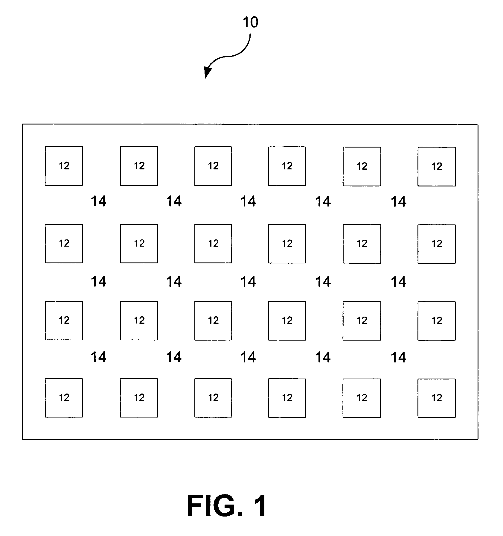
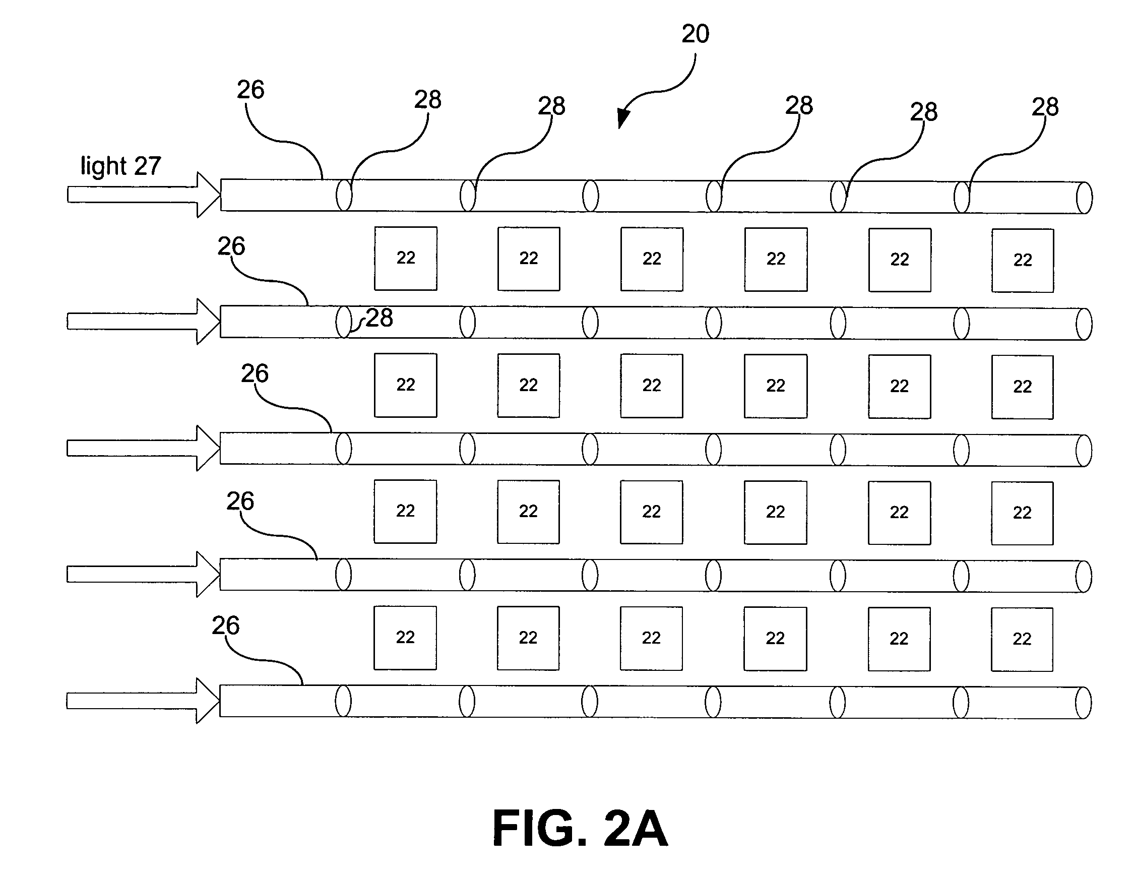
[0022]FIG. 1 depicts one example of an array of LEDs used to back-illuminate the LCD arrays in helmet-mounted displays (HMDs). Here, a typical array of LEDs illuminates a display in helmet mounted display environment. As one can see, array 10 of LED 12 is not continuous. It has a large amount of interstitial space 14 located amongst the LEDs. The present invention takes advantage of the interstitial space by providing a loom of fiber optics or other optical carriers as illustrated in FIGS. 2A and 2B. Here array 20 of LEDs 22 has interlaced with optical carriers 24 which provide additional illumination at the interstitial points within array 20.

[0023]FIG. 2A depicts an optical loom wherein leaky array fiber 26 transmits sunlight 27 or other illumination through leaky coupling slots 28. Individual leaky coupling ...


PUM

PropertyMeasurementUnit
brightnessaaaaaaaaaa
optical energyaaaaaaaaaa
flexibleaaaaaaaaaa

Abstract

The present invention provides an optical system and method that substantially eliminates or reduces disadvantages and problems associated with previously developed optical visual display systems and methods used for displaying critical visual symbology or rastered imagery in high ambient brightness environments.

Description

CROSS-REFERENCE TO RELATED APPLICATION[0001]This application claims the benefit of priority to U.S. Provisional Patent Application No. 60 / 544,595 filed on Feb. 13, 2004 entitled “METHOD FOR INCREASING DAYLIGHT DISPLAY BRIGHTNESS FOR HELMET MOUNTED DISPLAYS”, and is incorporated herein by reference in its entirety.GOVERNMENT INTEREST[0002]This invention was made with Government support under Contract Number N00019-02-C-3002 awarded by the Department of the Navy. The Government has certain rights in this invention.TECHNICAL FIELD OF THE INVENTION[0003]The present invention relates generally to optical systems and methods that increase display brightness, and more particularly, a system and method for pilot visual optical displays to increase the display brightness of a heads up or helmet-mounted display using ambient light.BACKGROUND OF THE INVENTION[0004]A helmet mounted or heads up visual display is often susceptible to illumination conditions where a viewer is incapable of seeing t...

Claims


Application Information

Patent Timeline
Patent Type & Authority Patents(United States)
IPC IPC(8): G02B6/04G02B6/06F21S11/00F21V8/00G02B3/00G02B3/08G02B6/00G02B27/00G02B27/01G02F1/13357
CPCG02B6/0006G02B6/0008G02B27/0172G02F1/133524G02F1/133603G02B6/4201F21S11/00G02B3/0056G02B3/08G02B6/00G02F2001/133626G02B2027/0118G02F2001/133607G02F2001/133618G02F1/133618G02F1/133626G02F1/133607
Inventor JONES, MICHAEL I.
Owner LOCKHEED MARTIN CORP
Why Eureka
Try Eureka