Cold storage

a technology of cold storage and cooling chamber, which is applied in the direction of defrosting, lighting and heating apparatus, and domestic cooling apparatus, etc., can solve the problems of inhibiting the adhesion•sealability of the thermal insulation box member, and achieve the effect of smooth treatment and smooth flow into the cooling chamber

Inactive Publication Date: 2008-10-07
SANYO ELECTRIC CO LTD
View PDF5 Cites 13 Cited by
  • Summary
  • Abstract
  • Description
  • Claims
  • Application Information

AI Technical Summary

Benefits of technology

[0012]Consequently, the cooling box is attached to the bottom wall of the thermal insulation box member without any problem, cold air circulation is constituted in such a manner that cold air which has exchanged heat with the cooler is discharged into the storage chamber by the air blower via the cold air discharge port, and sucked into the cooling chamber via the cold air suction port, and the inside of the storage chamber can be cooled. Especially, according to the present invention, since the only cooling box is pushed up, operation is lightened, and operability can be enhanced. As compared with a conventional constitution in which the whole cooling unit is pushed up toward the bottom wall of the thermal insulation box member, in the present invention, since the only cooling box is pushed up, a weight to be pushed up is reduced, the unit in an attached state lowers by its own weight, and a disadvantage that adhesion•sealability with respect to the thermal insulation box member is deteriorated can be inhibited.
[0015]Especially, in the invention, the pair of hanging rails are disposed on the opposite side upper portions of the cooling box, and the hanging rails are supported on the support rails of the bottom wall of the thermal insulation box member. Therefore, the end portions of the hanging rails can be laid and slid on the support rails, and the attaching operation of the cooling box is facilitated.
[0017]According to the present invention, in the above-described inventions, the thermal insulation box member comprises the inner box, the outer box, the insulating material filled between both the boxes and the like. Moreover, the openings are formed in the bottom faces of the inner and outer boxes constituting the bottom wall of the thermal insulation box member. The passage member constituting the cold air discharge port and the cold air suction port between both the openings is disposed in the insulating material. The upper end of the passage member is allowed to abut on the downward flange formed on the opening edge of the inner box bottom face on the side of the insulating material, and the lower end of the passage member is allowed to abut on the upward flange formed on the opening edge of the outer box bottom face on the non-insulating-material-side. Therefore, water discharged from the storage chamber can smoothly flow into the cooling chamber via the cold air discharge port and cold air suction port along the passage member without being interrupted by the passage member disposed on the edge portions of the cold air discharge and suction ports.
[0018]Moreover, since draining can be performed by the passage member disposed in the cold air discharge and suction ports, the water discharged from the storage chamber can be smoothly treated.
[0020]According to the present invention, in the above-described inventions, since the lower end of the passage member is attached to the upward flange from above, a draining effect can be increased, and water immersion on the insulating material side can be prevented.
[0022]According to the present invention, the above-described invention comprises: the overflow port formed in the cooling box; and the drainboard disposed under the cooler, and the drainboard comprises the barrier having the predetermined water passing portion on the windward side of passed air by the blower. Therefore, the water discharged from the storage chamber via the cold air discharge and suction ports can be smoothly passed downwards to the overflow port through the water passing portion of the barrier of the drainboard. Defrosted water generated in the cooler can be smoothly passed to the overflow port, and therefore a draining process can be smoothly performed.

Problems solved by technology

As compared with a conventional constitution in which the whole cooling unit is pushed up toward the bottom wall of the thermal insulation box member, in the present invention, since the only cooling box is pushed up, a weight to be pushed up is reduced, the unit in an attached state lowers by its own weight, and a disadvantage that adhesion•sealability with respect to the thermal insulation box member is deteriorated can be inhibited.

Method used


Image

  • Cold storage
  • Cold storage
  • Cold storage

Examples


Embodiment Construction

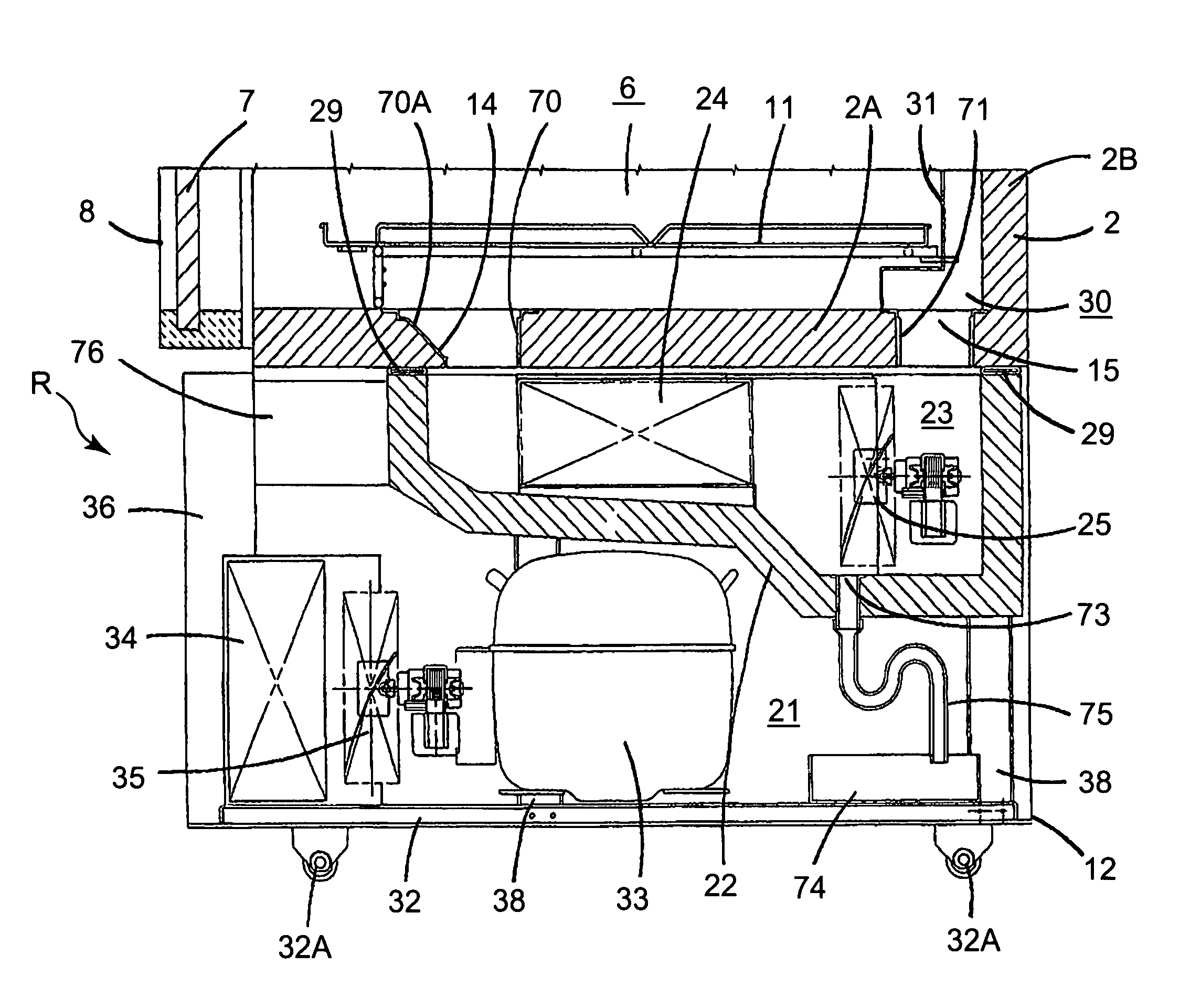
[0044]The present invention has been developed to solve conventional technique problems, and there is provided a cold storage in which a cooling box is attached to a bottom wall of a thermal insulation box member without any trouble, cold air circulation is constituted in such a manner that cold air which has exchanged heat with a cooler is discharged into a storage chamber by an air blower via a cold air discharge port, and sucked into a cooling chamber via a cold air suction port, and the inside of the storage chamber can be cooled. An embodiment of the present invention will be described hereinafter in detail with reference to the drawings.

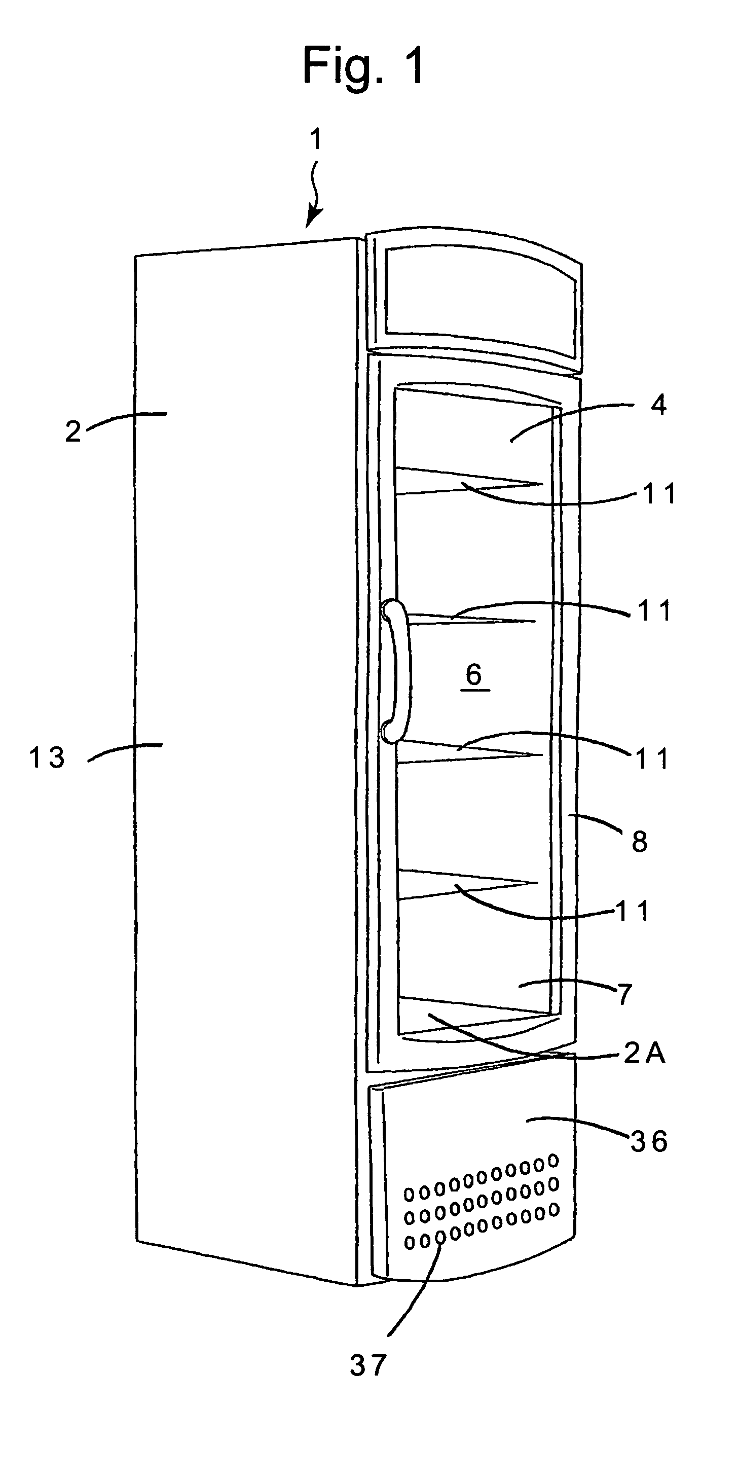
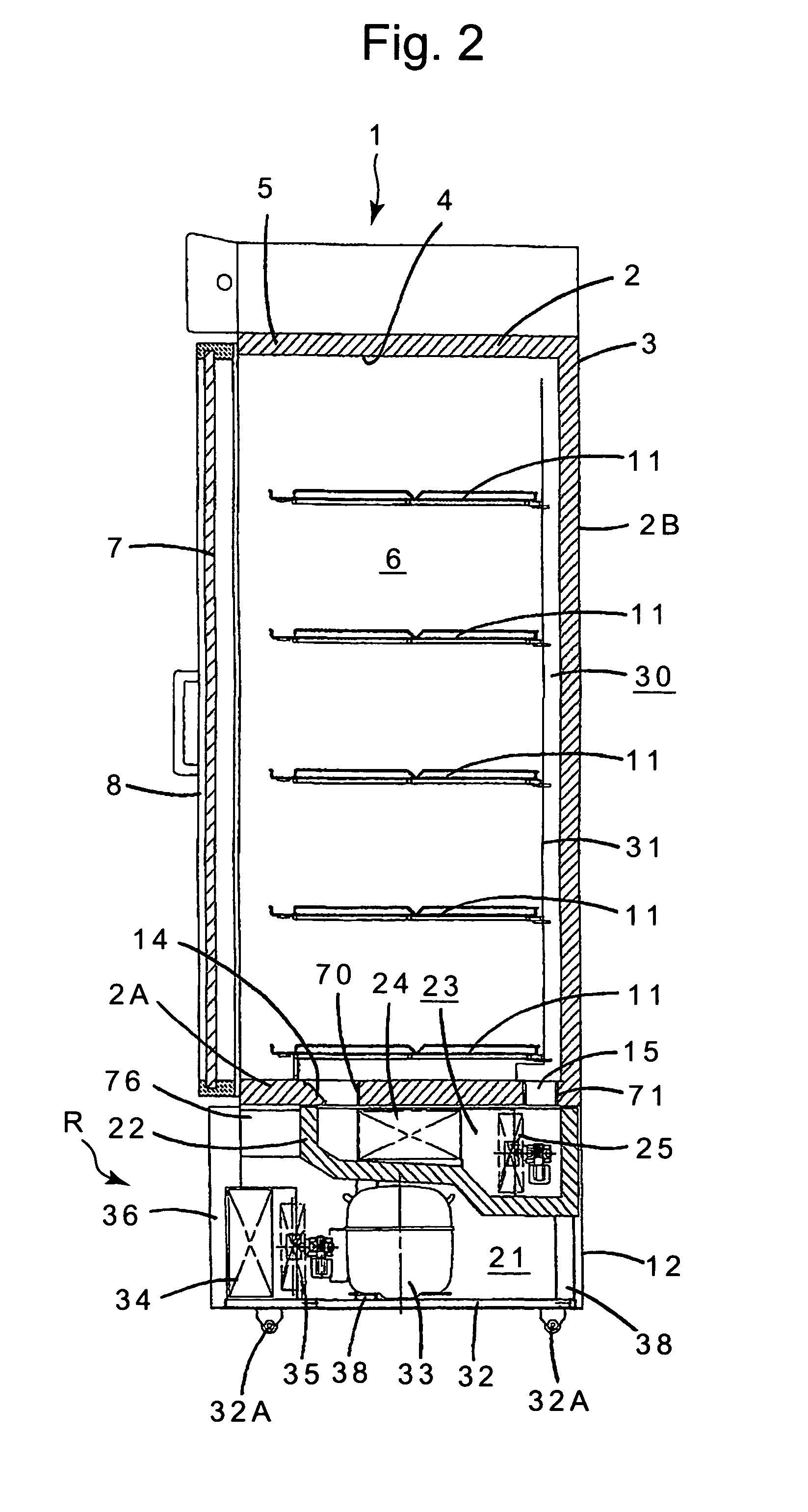
[0045]In a cold storage 1 of an embodiment, a main body is constituted by a rectangular thermal insulation box member 2 whose front face is opened. The thermal insulation box member 2 comprises: an outer box 3 having an opening in the front face and formed of a steel plate; an inner box 4 having an opening in the front face; and an insulating m...


PUM


Abstract

An object is to provide a cold storage in which a cooling box is attached to a bottom wall of a thermal insulation box member without any trouble, cold air circulation is constituted in such a manner that cold air which has exchanged heat with a cooler is discharged into a storage chamber by an air blower via a cold air discharge port, and sucked into a cooling chamber via a cold air suction port, and the inside of the storage chamber can be cooled. A mechanical chamber is constituted under the storage chamber constituted in the thermal insulation box member, and the cold storage comprises: a cooling unit in which a cooler and a blower contained in the cooling chamber constituted in the cooling box, a compressor, a condenser and the like are arranged and integrated; and the cold air discharge port and the cold air suction port which are formed in the bottom wall of the thermal insulation box member constituting a ceiling of the mechanical chamber and which connect the inside of the storage chamber to that of the mechanical chamber. The compressor, condenser and the like are disposed on an attachment base, the cooling box is disposed on the attachment base in such a manner as to be movable to upper / lower positions, and the only cooling box is pushed up in a direction of the bottom wall.

Description

BACKGROUND OF THE INVENTION[0001]The present invention relates to a cold storage in which a cooling unit comprising a compressor or a cooler is incorporated under a thermal insulation box member containing a storage chamber.[0002]In this type of cold storage 100 which has heretofore been used as a low-temperature showcase, as shown in FIG. 18 which is an enlarged sectional view of a lower part of the cold storage 100, a mechanical chamber 103 is constituted under a storage chamber 102 constituted in a thermal insulation box member 101, and a cold air discharge port 104 and a cold air suction port 105 which communicate with the inside of the mechanical chamber 103 are formed in a bottom wall 101A of the thermal insulation box member 101. A cooling box 106 having an opening in an upper face thereof is disposed in the mechanical chamber 103 in such a manner as to abut on the bottom wall 101A of the thermal insulation box member 101, and a cooler 107 and a cooler air blower 108 constitu...

Claims


Application Information

Patent Timeline
Patent Type & Authority Patents(United States)
IPC IPC(8): A47F3/04F25B21/02F25D11/00F25D11/04F25D17/04F25D17/06F25D19/00F25D19/02F25D21/14F25D23/00
CPCF25D19/02F25D21/14F25D17/062F25D2400/38F25D2317/0671F25D2321/146F25D2317/0651
Inventor IGUCHI, HARUNOBUYONEHARA, YUJI
Owner SANYO ELECTRIC CO LTD
Why Eureka
Try Eureka