Burner with center air jet

a fuel burner and air jet technology, applied in the field of fuel burners, can solve the problems of forming long flames, affecting boiler operation, and consuming a lot of fuel, and achieve the effect of reducing nox emissions

Active Publication Date: 2008-10-07
THE BABCOCK & WILCOX CO
View PDF34 Cites 26 Cited by
  • Summary
  • Abstract
  • Description
  • Claims
  • Application Information

AI Technical Summary

Benefits of technology

[0010]The present invention solves the aforementioned problems associated with delayed combustion produced by typical low NOx burners and introduces a new burner apparatus and method of combusting fossil fuels to further reduce NOx emissions in commercial and utility boilers.
[0011]A burner according to the present invention is suitable for firing pulverized coal (PC) or gaseous hydrocarbons. The present invention comprises an axial zone concentrically surrounded by a first annular zone. The first annular zone provides fuel to the burner at a predetermined velocity so as to create a fuel jet exiting the burner and subsequently forming a burner flame via combustion in the presence of oxygen. The axial zone produces a center air jet piercing the burner flame along its internal axis. The center air jet provides oxygen along the center axis of the burner flame, allowing the flame to combust from the inside out, while maintaining an overall fuel rich environment in the flame root thereby suppressing NOx formation.
[0012]Additional oxygen supplied by second and third annular zones concentrically surrounding the first annular zone further reduces NOx formation while providing a means for accelerating combustion. Flow conditioning devices of the second and third annular zones aerodynamically suppress fuel jet expansion. Within this aerodynamic suppression, swirl from the air exiting the second and third annular zones creates an internal recirculation zone along the outer boundary of the flame zone which inhibits NOx formation. The internal recirculation zone (IRZ) causes NOx formed along the outer air-rich periphery of the flame to recirculate back into the fuel rich flame core. The hotter flame temperature, resulting from the inside out combustion of the center air jet, cause uncombusted hydrocarbon radicals to scavenge available oxygen within the IRZ, thereby suppressing the formation of NOx, and reducing NO back to other nitrogenous species. A wider, shorter flame envelope results as flame temperature increases due to the accelerated combustion of fuel from the inside out and outside in within the IRZ.
[0013]Another aspect of the present invention can be considered a method of reducing NOx emissions in a center air jet burner comprising, providing a burner having an axial zone concentrically surrounded by a first annular zone, providing the axial zone with a first gas comprising oxygen, wherein the first gas exits the axial zone at a velocity between about 5000 ft / min and about 10,000 ft / min, providing the first annular zone with a carrier gas comprising a pulverized coal, wherein the carrier gas exits the axial zone at a velocity between about 3000 ft / min and about 5000 ft / min.
[0014]Yet another aspect of the present invention can be considered a method of reducing NOx emissions in a center air jet burner comprising, providing a four zone burner, wherein the innermost zone is an axial zone concentrically surrounded by a first annular zone, which in turn is concentrically surrounded by a second annular zone, which in turn is concentrically surrounded by a third annular zone, providing the axial zone with a first gas comprising oxygen, providing the first annular zone with a carrier gas comprising a pulverized coal, providing the second annular zone with a second gas comprising oxygen, providing the third annular zone with a third gas comprising oxygen, providing the burner with the carrier gas at a velocity greater than about 3000 ft / min, providing the burner with the first gas at a velocity greater than the carrier gas, providing the burner with the second gas at a velocity less than the carrier gas, providing the burner with the third gas at a velocity greater than the carrier gas, combusting the pulverized coal in the carrier gas stream from the inside of the stream with the first gas, combusting the pulverized coal in the carrier gas stream from the outside with the second gas and the third gas, utilizing the velocity gradient between the four annular zones to create a recirculation zone within a burner flame, suppressing NOx formation and accelerating combustion by recirculation of uncombusted coal and oxygen in the burner flame.

Problems solved by technology

Unlike conventional burners, low NOx burners tend to form long flames and produce higher levels of unburned combustibles.
Long flames are not always desirable as they may be incompatible with furnace depth or height, and can impair boiler operation by causing flame impingement, slagging, and / or boiler tube corrosion.
Long flames result from an insufficient air supply to the fuel jet as it proceeds into the furnace.
SA from the outer air zones of low NOx burners do not effectively penetrate the downstream fuel jet, such that unburned fuel persists due to a lack of air supply along the flame axis.
High levels of unburned fuel are undesirable in both furnaces with OFA and those without.
Unburned combustibles in the form of unburned carbon and CO reduce boiler efficiency and add operation expenses, whereas unburned pulverized coal, by nature of its abrasiveness, may cause undesirable erosive damage to the furnace itself.
Incomplete air / fuel mixing ahead of an OFA system can cause excessive amounts of unburned fuel to persist up to the OFA ports.
In addition it becomes increasingly difficult to completely burn out these combustibles at and beyond the OFA ports, such that they add to inefficiency and operational difficulties.

Method used


Image

  • Burner with center air jet
  • Burner with center air jet
  • Burner with center air jet

Examples


Embodiment Construction

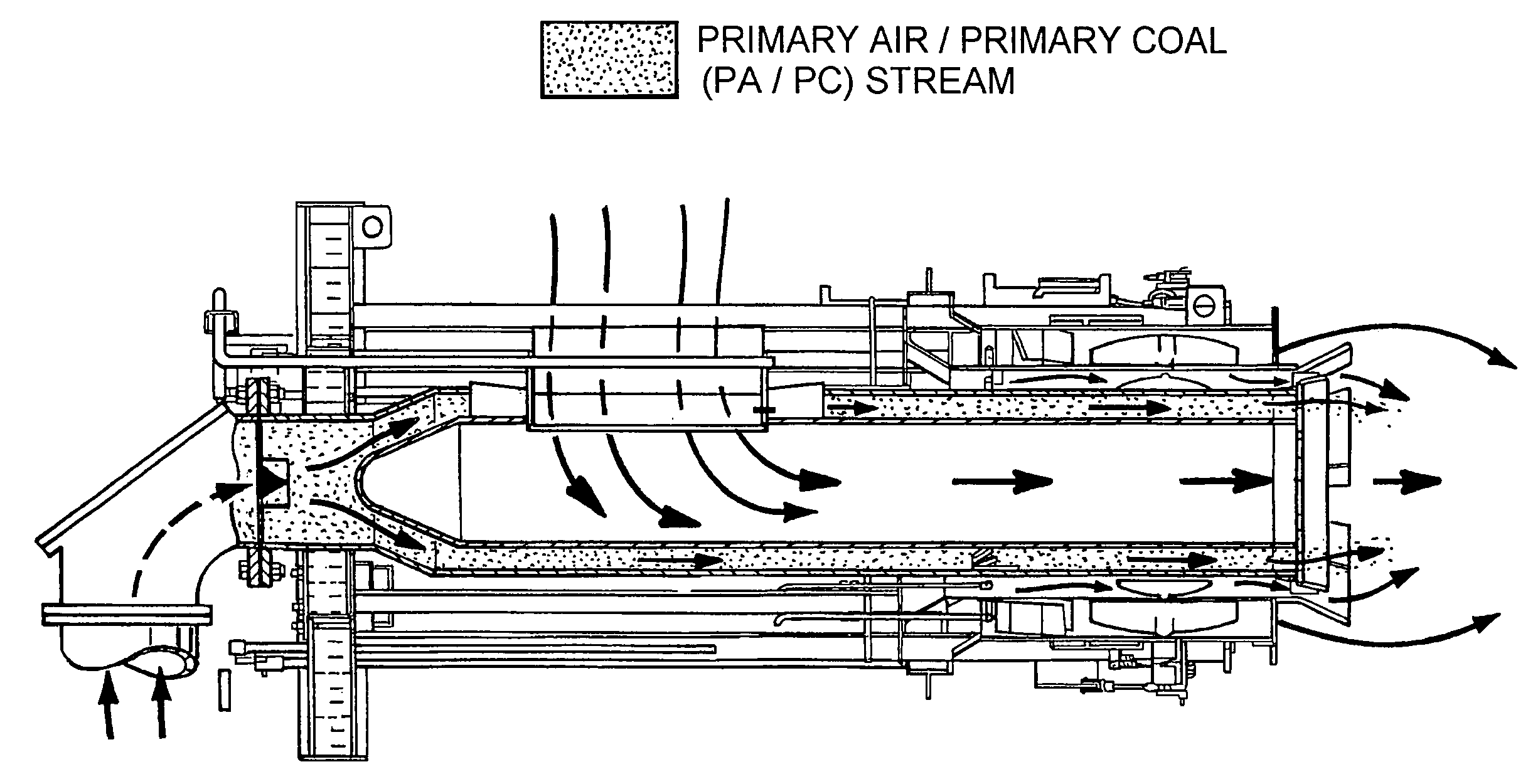
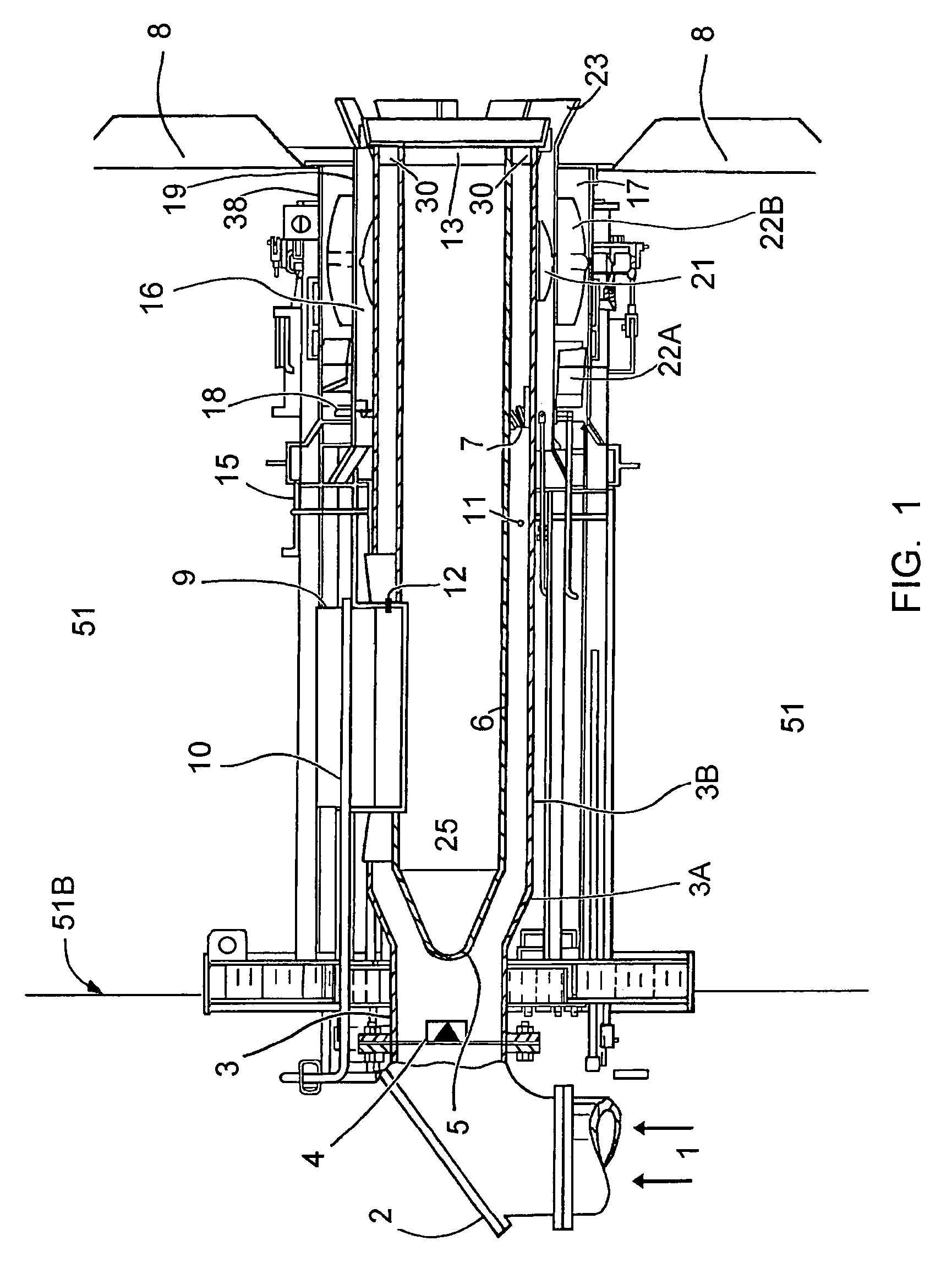
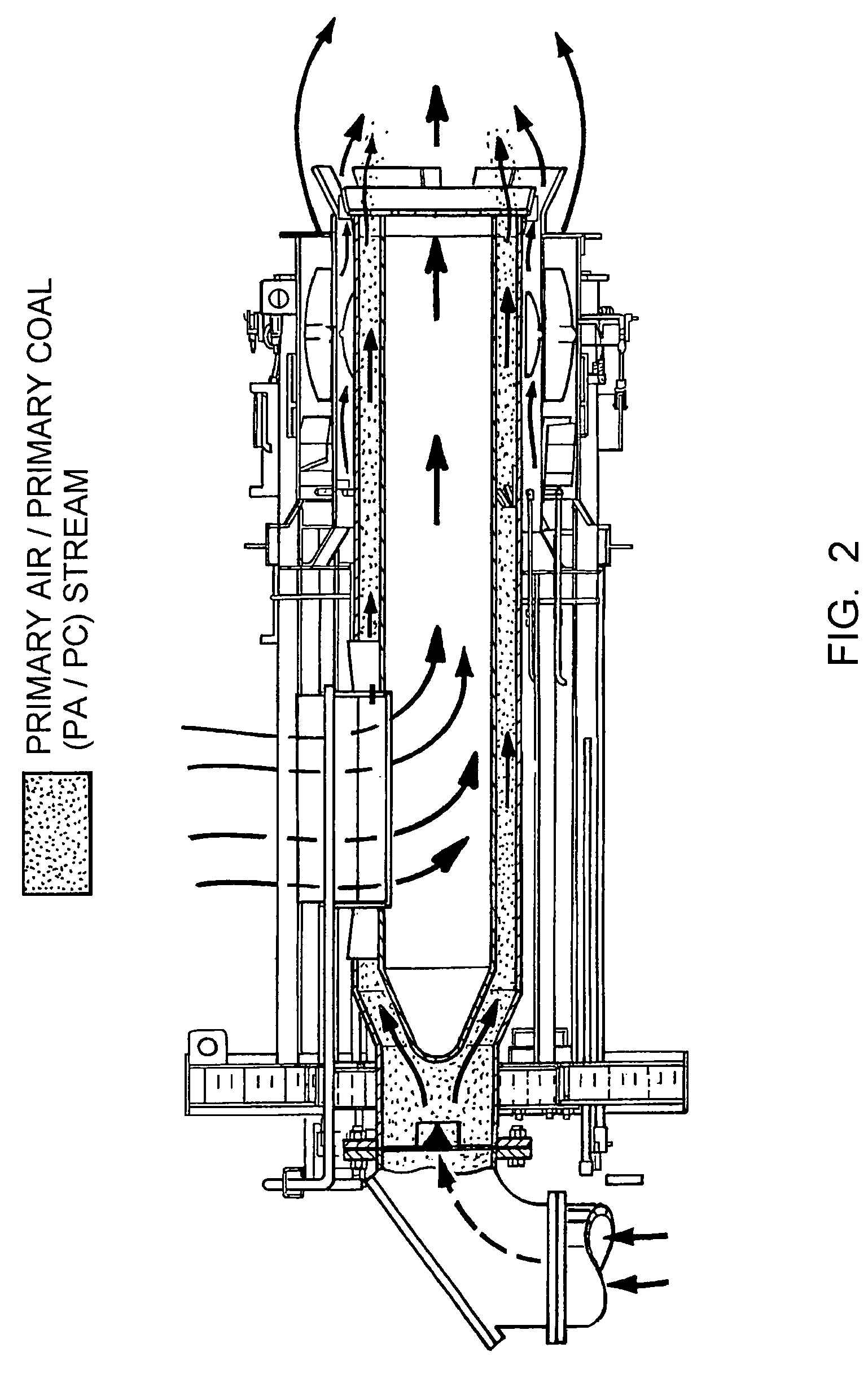
[0020]Referring to the drawings, generally where like numerals designate the same or functionally similar features, throughout the several views and first to FIG. 1, there is shown a schematic sectional view of a burner depicted in accordance with the present invention. Axial pipe 6, defining an axial zone 25 therein, is concentrically surrounded by a first annular pipe 3 wherein the area between the two pipes defines a first annular zone 11. Radially interposed between a portion of first annular pipe 3 and axial pipe 6 is feeder duct 9 such that axial pipe 6 and windbox 51 are in fluid communication with opposite ends of feeder duct 9.

[0021]Referring now to FIG. 3, a top view of feeder duct 9 radially interposed between at least a portion of first annular pipe 3 and axial pipe 6 (not shown in FIG. 3) is provided, such that axial pipe 6 and windbox 51 are in fluid communication with opposite ends of feeder duct 9.

[0022]Referring back to FIG. 1, secondary air is supplied by forced dr...


PUM


Abstract

A new burner apparatus and method of combusting fossils fuels for commercial and industrial application is provided wherein the new burner apparatus achieves low NOx emissions by supplying oxygen to the center of the burner flame in as manners so as to create a fuel rich internal combustion zone within the burner flame.

Description

FIELD OF THE INVENTION[0001]The present invention relates generally to fuel burners and, in particular, to a new and useful pulverized coal burner and method of combustion which achieves low NOx emissions by supplying oxygen directly to the center of the burner flame in a manner so as to create a fuel rich internal combustion zone within the burner flame and accelerate fuel combustion.BACKGROUND OF THE INVENTION[0002]NOx is a byproduct produced during the combustion of coal and other fossil fuels. Environmental concerns regarding the effects of NOx have prompted enactment of NOx emissions regulations requiring sharp NOx emission reductions from industrial and utility power plants in several countries including the United States. Current commercial methods and apparatuses for reducing NOx emissions have been successful in lowering NOx emissions from the levels emitted in previous years; however, further advances, beyond those of currently known methods and apparatuses, are needed to ...

Claims


Application Information

Patent Timeline
Patent Type & Authority Patents(United States)
IPC IPC(8): F23D1/00F23D1/04
CPCF23C7/008F23C9/003F23D1/00F23C2201/20F23C2900/06043
Inventor LARUE, ALBERT D.SAYRE, ALAN N.KAHLE, WILLIAM J.SARV, HAMIDROWLEY, DANIEL R.
Owner THE BABCOCK & WILCOX CO
Why Eureka
Try Eureka