
Engine exhaust valve timing and lift system for a two-stroke locomotive diesel engine having an egr system

a two-stroke locomotive and engine technology, applied in the field of locomotive diesel engines, can solve the problems of high fuel efficiency and achieve the effect of reducing nox emissions

Inactive Publication Date: 2011-02-03
ELECTRO-MOTIVE DIESEL
View PDF6 Cites 1 Cited by
  • Summary
  • Abstract
  • Description
  • Claims
  • Application Information

AI Technical Summary

Benefits of technology

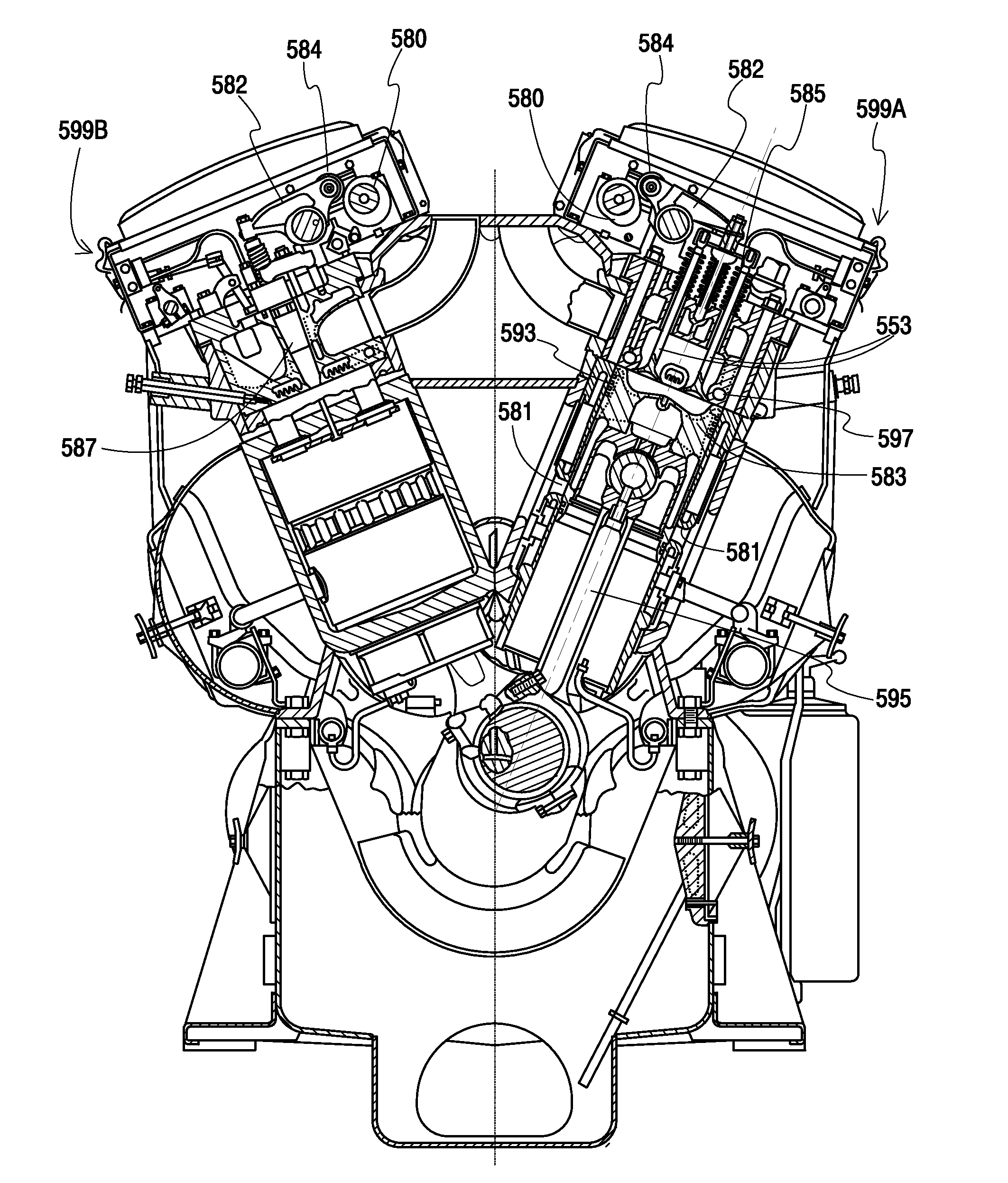
[0012]The present invention generally relates to a diesel engine and, more particularly, to an engine exhaust valve timing and lift system for a uniflow two-stroke locomotive diesel engine having an EGR system. This system and method reduce NOx emissions while attaining desired levels of cylinder scavenging and mixing. Specifically, the present invention engine exhaust valve system controls the timing, lift and velocity of exhaust valve opening and closing in order to attain the desired NOx emission levels and the desired levels of cylinder scavenging and mixing.
[0013]Specifically, a method for phasing an exhaust cam is provided for a diesel engine having a piston and an exhaust gas recirculation (EGR) system adapted to reduce NOX emissions and achieve desired fuel economy by recirculating exhaust gas through the engine. The method generally includes the steps of providing a camshaft for actuating an exhaust cam for actuating at least one exhaust valve, wherein the exhaust cam has a lobe and a centerline, and is situated on said camshaft and in relation to top dead center of the piston; opening the exhaust valve at a slow constant velocity from about 79 degrees to about 108 degrees past top dead center; maximizing lift of the exhaust valve at about 177 degrees past top dead center at the beginning of compression; and closing the exhaust valve at about 261 degrees past top dead center.

Problems solved by technology

Traditional systems have been implemented which reduce these pollutants, but at the expense of fuel efficiency.

Method used


Image

  • Engine exhaust valve timing and lift system for a two-stroke locomotive diesel engine having an egr system
  • Engine exhaust valve timing and lift system for a two-stroke locomotive diesel engine having an egr system
  • Engine exhaust valve timing and lift system for a two-stroke locomotive diesel engine having an egr system

Examples


Embodiment Construction

[0029]The present invention is directed to an engine exhaust valve timing and lift system for a uniflow two-stroke locomotive diesel engine having an EGR system. This system and method reduces NOx emissions while attaining desired levels of cylinder scavenging and mixing. Specifically, the present invention engine exhaust valve system controls the timing, lift and velocity of exhaust valve opening and closing in order to attain the desired NOx emission levels and the desired levels of cylinder scavenging and mixing.

[0030]In order to meet at least U.S. EPA Tier III emission standards, as well as the more stringent European Commission Tier IIIb NOX emission requirements, several key design changes have been made to the locomotive system of FIG. 3. As shown in FIG. 4, an EGR system 450 is illustrated which recirculates through the engine 406 exhaust gases from the exhaust manifold 412 of the engine 406, mixes the exhaust gases with the cooled charge air of the aftercooler 420, and deli...


PUM


Abstract

The present invention is directed to an engine exhaust valve timing and lift system for a uniflow two-stroke locomotive diesel engine having an EGR system. This system and method reduces NOx emissions while attaining desired levels of cylinder scavenging and mixing. Specifically, the present invention engine exhaust valve system controls the timing, lift and velocity of exhaust valve opening and closing in order to attain the desired NOx emission levels and the desired levels of cylinder scavenging and mixing.

Description

CROSS-REFERENCE TO RELATED APPLICATIONS[0001]This application is a Nonprovisional patent application, which claims benefit to U.S. Provisional Application Ser. No. 61 / 230,698, entitled “Exhaust Gas Recirculation System for a Locomotive Two-Stroke Uniflow Scavenged Diesel Engine,” filed Aug. 1, 2009, the complete disclosure thereof being incorporated herein by reference.TECHNICAL FIELD[0002]This invention relates to a locomotive diesel engine and, more particularly, to an engine exhaust valve timing and lift system for a two-stroke locomotive diesel engine having an exhaust gas recirculation system.BACKGROUND OF THE INVENTION[0003]The present invention generally relates to a locomotive diesel engine and, more particularly, to an engine exhaust valve timing and lift system for a two-stroke locomotive diesel engine having an exhaust gas recirculation (“EGR”) system. This system and method reduces NOx emissions while attaining desired levels of cylinder scavenging and mixing. Specifical...

Claims


Application Information

Patent Timeline
IPC IPC(8): F02B47/08F01L1/34
CPCY02T10/121Y02T10/125F02B25/145F02B23/0696F02B47/08F02F3/26Y02T10/12
Inventor HEILENBACH, JAMES W.REXAVIER, RAJIMORAVEC, KEITH E.ALBRIGHT, RANDAL K.
Owner ELECTRO-MOTIVE DIESEL
Learn More