Boost control for internal combustion engine using substantially carbon-free fuel

a technology of internal combustion engine and substantially carbon-free fuel, which is applied in the direction of electric control, machines/engines, mechanical equipment, etc., can solve the problems of reducing the performance level by about 14%, increasing the displacement of the engine, and increasing the weight of the engine. , to achieve the effect of reducing nox emissions, increasing the displacement of the engine, and increasing the weight of the engin

Inactive Publication Date: 2007-10-09
FORD GLOBAL TECH LLC
View PDF9 Cites 0 Cited by
  • Summary
  • Abstract
  • Description
  • Claims
  • Application Information

AI Technical Summary

Benefits of technology

[0005]While the inventor herein has recognized that operating a substantially carbon-free engine in a lean condition can reduce NOx emissions, the inventor has also recognized that running such an engine lean can make it difficult to achieve comparable power output. In an attempt to compensate for decreased power output in internal combustion engines, attempts have been made to increase engine displacement. However, such an approach can increase the weight of the engine, which can adversely affect vehicle fuel efficiency.
[0006]At least some of the issues associated with using substantially carbon-free fuel may be addressed by combusting a substantially carbon-free fuel at an equivalence ratio less than 1, while boosting intake air pressure. In this way, it may be possible to limit HC, CO, CO2, and / or NOx emissions, while maintaining satisfactory power output and vehicle fuel efficiency.

Problems solved by technology

As part of the conversion, the fuel can be combusted, thus causing hot combustion products to expand within the engine.
Combustion reactions can have several products, or emissions, some of which can be undesirable.
In particular, while hydrogen fueled engines have low levels of HC, CO, and CO2 emissions, thus far, hydrogen engines have proven to have significant levels of NOx emissions.
Under such conditions, the engine is also very susceptible to auto-ignition and the performance level will be reduced by about 14% compared to a comparable spark-ignited gasoline engine.
While the inventor herein has recognized that operating a substantially carbon-free engine in a lean condition can reduce NOx emissions, the inventor has also recognized that running such an engine lean can make it difficult to achieve comparable power output.
However, such an approach can increase the weight of the engine, which can adversely affect vehicle fuel efficiency.

Method used


Image

  • Boost control for internal combustion engine using substantially carbon-free fuel
  • Boost control for internal combustion engine using substantially carbon-free fuel
  • Boost control for internal combustion engine using substantially carbon-free fuel

Examples


Embodiment Construction

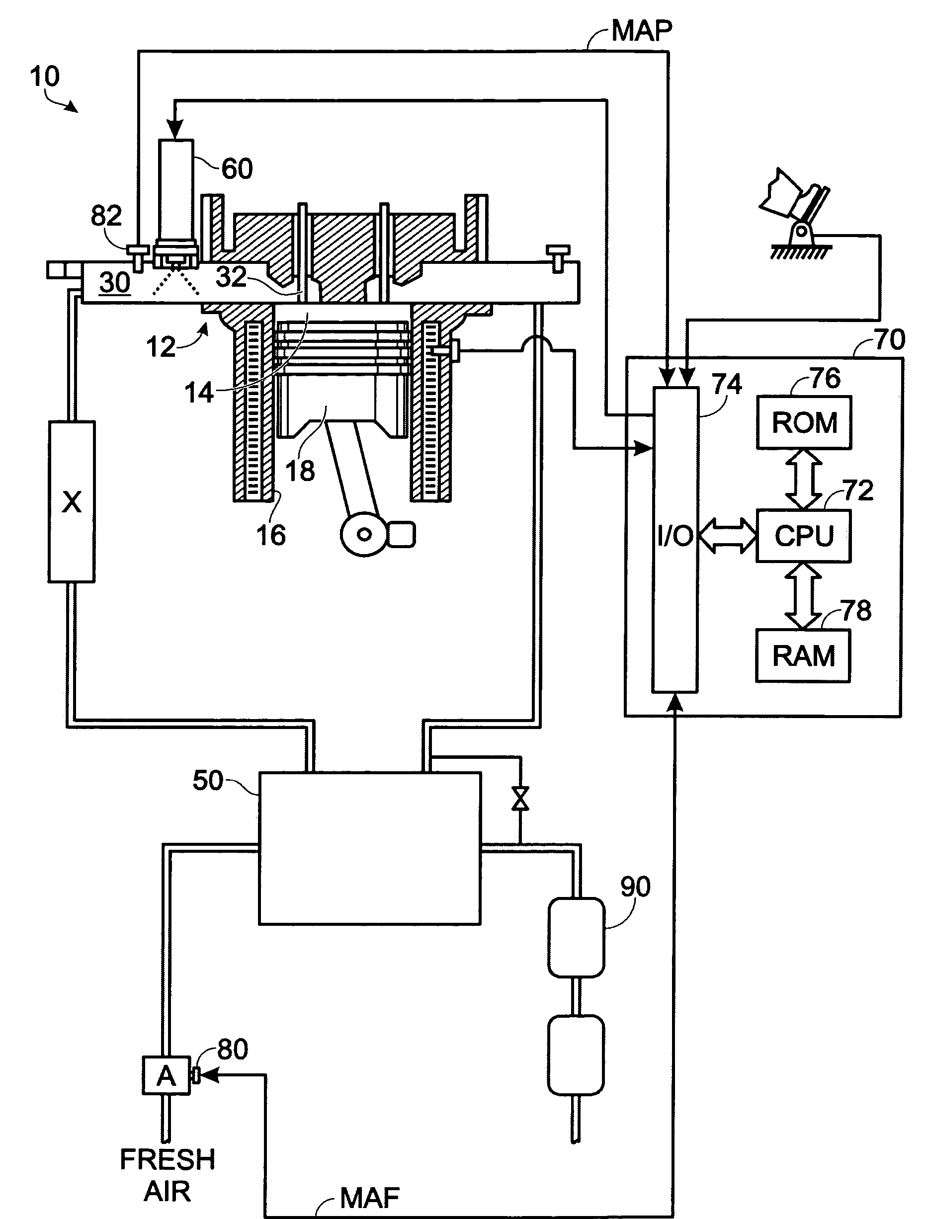
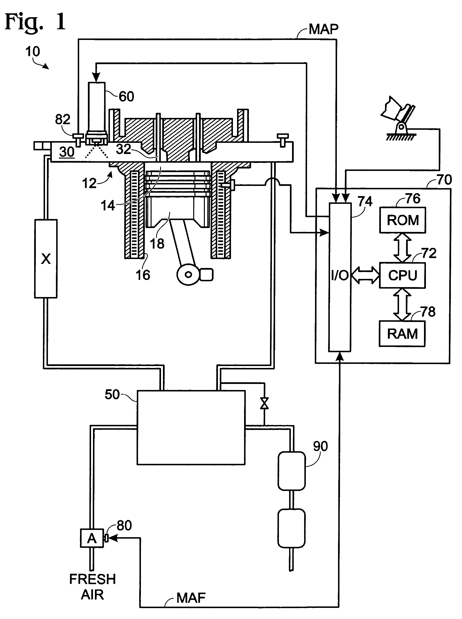
[0011]The present disclosure relates to a strategy for controlling boost in an internal combustion engine configured to use a substantially carbon-free fuel (such engines are herein referred to as substantially carbon-free engines). Hydrogen (H2) may be used as a substantially carbon-free fuel in accordance with this disclosure, although that is not required.

[0012]FIG. 1 schematically shows an internal combustion engine 10 that is configured to convert substantially carbon-free fuel into mechanical energy. Engine 10 may include one or more cylinders, one of which is illustrated at 12. Cylinder 12 includes a combustion chamber 14 at least partially defined by cylinder walls 16 and a moveable piston 18.

[0013]Combustion chamber 14 is in fluid communicates with an air intake manifold 30 via intake valve 32. The air intake manifold can be used to deliver air, including oxygen (O2), to the combustion chamber for combustion. The intake valve can be controlled so that a desired flow of air ...


PUM


Abstract

A system and method for limiting HC, CO, CO2, and NOx emissions in an internal combustion engine is provided. According to one aspect of the disclosure, a substantially carbon-free fuel, such as hydrogen (H2), is used to fuel combustion in an internal combustion engine. The internal combustion engine is operated, at least some of the time, at an equivalence ratio less than 1 and a boost pressure ratio greater than 1.

Description

FIELD [0001]The present disclosure is directed toward a system and method for limiting exhaust emissions while maintaining power output and fuel energy efficiency in an internal combustion engine.BACKGROUND AND SUMMARY [0002]Internal combustion engines convert chemical energy in a fuel to mechanical energy. As part of the conversion, the fuel can be combusted, thus causing hot combustion products to expand within the engine. The expansion of the combustion products can be used to move mechanical components of the engine, such as pistons. Combustion reactions can have several products, or emissions, some of which can be undesirable. For example, when hydrocarbons are used as fuel, combustion products can include HC, CO, CO2 and NOx.[0003]In an attempt to reduce emissions, efforts have been made to utilize substantially carbon-free hydrogen as a combustion fuel instead of hydrocarbons. When hydrogen (H2) is used as the fuel, there is not a substantial amount of HC, CO, or CO2 emission...

Claims


Application Information

Patent Timeline
Patent Type & Authority Patents(United States)
IPC IPC(8): F02B43/00F02B33/00F02D23/00
CPCF01N3/0807F01N13/0093F02B37/00F02B43/00F02D23/00F02D41/0007F02D41/0027F02M21/0206F02D19/024F01N13/009F01N3/0842F02B37/18Y02T10/144Y02T10/32F02M21/0278Y02T10/12Y02T10/30
Inventor NATKIN, ROBERT
Owner FORD GLOBAL TECH LLC
Why Eureka
Try Eureka