Evaporative emission canister purge actuation monitoring system

a technology of actuation monitoring and evaporative emission canister, which is applied in the direction of liquid fuel feeder, machine/engine, combustion air/fuel air treatment, etc., can solve the problems of affecting the environment, being relatively complex and costly, and expensive to service, so as to reduce the number of components, effectively monitor, and be inexpensive to manufacture

Inactive Publication Date: 2008-10-07
MAHLE INT GMBH
View PDF20 Cites 5 Cited by
  • Summary
  • Abstract
  • Description
  • Claims
  • Application Information

AI Technical Summary

Benefits of technology

[0011]In this way, the canister purge actuation monitoring system of the present invention reduces the number of components needed to effectively monitor the evaporative emission system as well as the complicated onboard plumbing of the type required for systems known in the related art. The system senses the presence and duration of a purge vacuum that is imposed on the vapor canister when the canister purge valve is open and also senses the presence of a leak in the evaporative emission system, to the extent this condition occurs. The evaporative emission canister purge actuation monitoring system of the present invention is inexpensive to manufacture and easy to service in the field. Moreover, it has an improved response time and accurate repeatability when compared to known systems in the related art. Finally, the evaporative emission canister purge actuation monitoring system is designed so as to present a smaller, less bulky profile. Accordingly, it is easier to “package” the evaporative emission canister purge actuation monitoring system of the present invention on the vehicle.

Problems solved by technology

Gasoline is a volatile substance that generates gasses that, if untreated, are harmful to the environment.
While on-board diagnostic evaporative emission systems of the type proposed in the related art have generally worked for their intended purposes they have also suffered from the disadvantage of being relatively complex and costly.
This objective is not always met in evaporative emission systems known in the related art and they can be expensive to service.

Method used


Image

  • Evaporative emission canister purge actuation monitoring system
  • Evaporative emission canister purge actuation monitoring system
  • Evaporative emission canister purge actuation monitoring system

Examples


Embodiment Construction

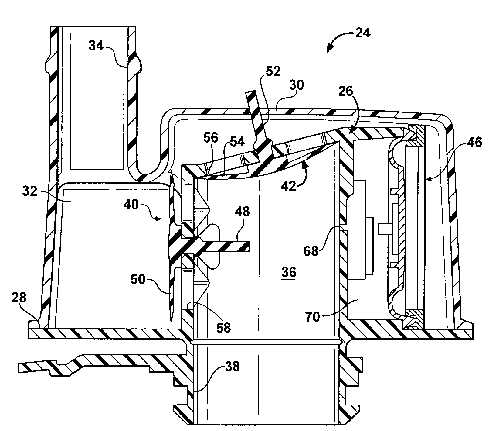
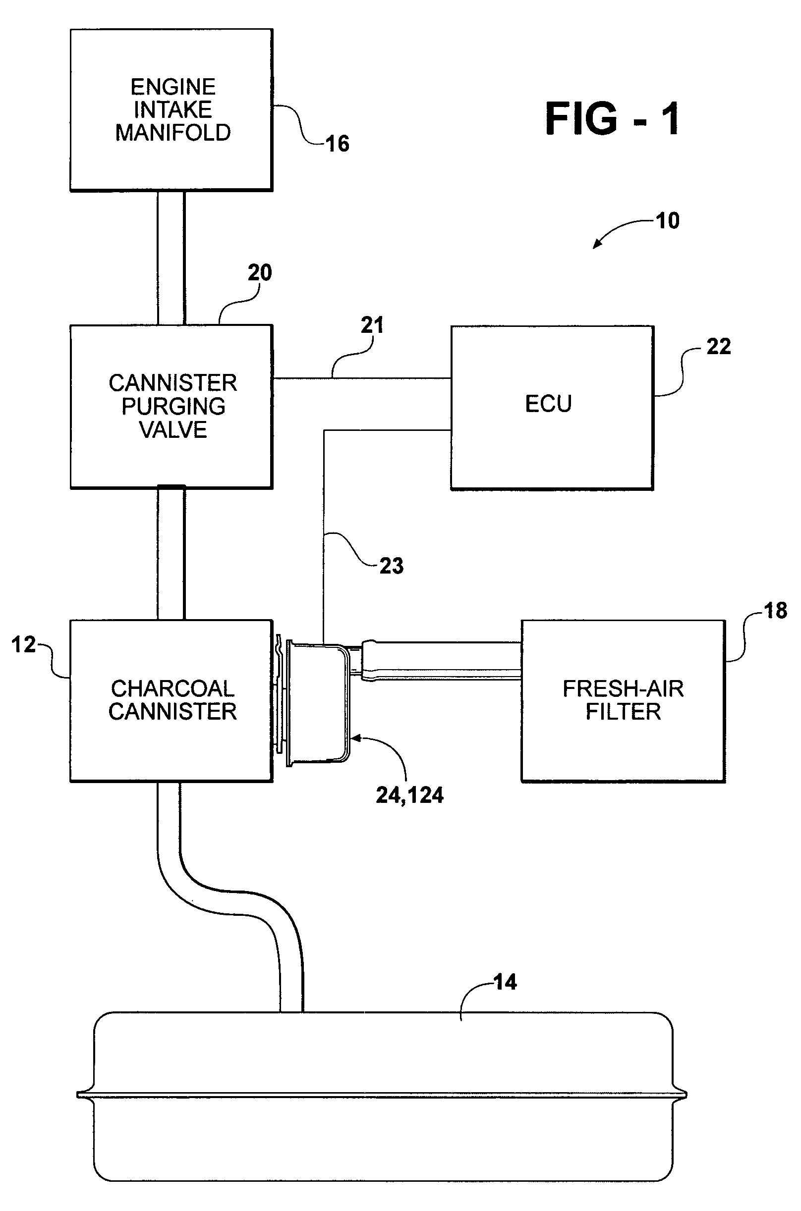
[0022]Referring now to the drawings, a representative evaporative emission system for an automotive vehicle is schematically illustrated at 10 in FIG. 1. The evaporative emission system 10 generally includes a vapor canister 12 operatively connected in fluid communication with a fuel tank 14 as well as the intake manifold 16 of the internal combustion engine. The vapor canister 12 is typically provided in fluid communication with the ambient air via a fresh air filter schematically indicated at 18 in FIG. 1. The vapor 12 canister typically includes carbon or some other absorbent material that acts to trap the volatile evaporative emissions generated by the fuel system. However, those having ordinary skill in the art will appreciate from the description that follows that the present invention is not limited to any particular type of vapor canister. A canister purge valve, generally indicated at 20, controls the flow of evaporative emissions between the vapor canister 12 and the intak...


PUM


Abstract

An evaporative emission canister purge actuation monitoring system includes an integrated valve body having a main flow passage, a first one-way umbrella valve mounted to the valve body that is responsive to predetermined positive pressure in the main flow passage to control flow of fluid from a vapor canister to ambient air as well as a second one-way umbrella valve that is responsive to a predetermined negative pressure in the main flow passage to control the flow of ambient air through a fresh air port. A vacuum actuated switch is supported by the integrated valve body and in electrical communication with a control unit. The switch is responsive to negative pressure in the main flow passage to send a signal indicative of the predetermined negative pressure to the control unit.

Description

BACKGROUND OF THE INVENTION[0001]1. Field of the Invention[0002]The present invention is directed toward an evaporative emission canister purge actuation monitoring system for a motor vehicle having a vapor canister, an engine, and at least one control unit.[0003]2. Description of the Related Art[0004]Automotive vehicles include fuel delivery systems having a fuel tank and fuel delivery lines. The fuel delivery lines typically include a plurality of conduits and associated connections operatively interconnecting the fuel tank with an internal combustion engine. A fuel pump is used to deliver the fuel under pressure from the tank to the engine via the fuel delivery lines. Many automotive vehicles are powered using gasoline as fuel. Gasoline is a volatile substance that generates gasses that, if untreated, are harmful to the environment. These gasses are generally referred to as evaporative emissions. Because they are gasses, these emissions can escape from the fuel system even throug...

Claims


Application Information

Patent Timeline
Patent Type & Authority Patents(United States)
IPC IPC(8): F02M37/04
CPCF02M25/0836F02M25/089F02M25/08F02M33/02B60K15/035
Inventor XIA, ZHOUXUANMULKERAN, KEVINCHAN, WINGJENSEN, HANS
Owner MAHLE INT GMBH
Why Eureka
Try Eureka