Automatic transmission having a pressure regulator with flow force compensation

a technology of automatic transmission and flow force compensation, which is applied in the direction of pressure relieving devices on sealing faces, process and machine control, instruments, etc., can solve the problems of affecting the operation of the machine, and requiring a large physical interaction on the part of the operator, so as to reduce the effect of flow force inherent, accurate and stable line hydraulic pressure, and high stability of line pressure control

Active Publication Date: 2008-10-07
BORGWARNER INC
View PDF16 Cites 19 Cited by
  • Summary
  • Abstract
  • Description
  • Claims
  • Application Information

AI Technical Summary

Benefits of technology

[0023]In this manner, the automatic transmission of the present invention having a pressure regulator with flow force compensation provides the advantages of highly stable and accurate control of the line pressure regardless of steady state flow and transient flow conditions. The present invention includes a shaped valve member and ports that direct the hydraulic flow through the pressure regulator in such a manner as to reduce the effects of the flow forces inherent in the flow of the regulated hydraulic fluid moving through the regulator. This provides extremely accurate and stable line hydraulic pressure resulting in accurate and efficient control of the transmission, which translates into improved the efficiency of the transmission and the vehicle.

Problems solved by technology

One disadvantage of the manual transmission is that there is an interruption in the drive connection during gear shifting.
This results in losses in efficiency.
In addition, there is a great deal of physical interaction required on the part of the operator to shift gears in a vehicle that employs a manual transmission.
Although conventional automatic transmissions avoid an interruption in the drive connection during gear shifting, they suffer from the disadvantage of reduced efficiency because of the need for hydrokinetic devices, such as torque converters, interposed between the output of the engine and the input of the transmission for transferring kinetic energy therebetween.
In addition, automatic transmissions are typically more mechanically complex and therefore more expensive than manual transmissions.
Fluid couplings have inherent slip.
The inherent slip reduces the efficiency of the torque converter.
While torque converters provide a smooth coupling between the engine and the transmission, the slippage of the torque converter results in a parasitic loss, thereby decreasing the efficiency of the entire powertrain.
The power required to drive the pump and pressurize the fluid introduces additional parasitic losses of efficiency in the automatic transmission.
However, even with the inherent improvements of these newer automated transmissions, they still have an operative power interruption in the drive connection between the input shaft and the output shaft during sequential gear shifting.
Power interrupted shifting results in a distinct shift feel that is generally associated with manual transmissions and may considered undesirable in certain operating environments.
While these new types of automatic transmissions have overcome several drawbacks associated with conventional transmissions, it has been found that controlling and regulating these automatically actuated transmissions to achieve the desired vehicle occupant comfort goals in an efficient and cost effective manner is a complicated matter.
Since hydraulically actuated devices respond in a predetermined and a precise manner for the given pressure supplied to actuate them, inaccurate control of the hydraulic supply pressure causes inaccurate operation and control of a AMT or DCT transmission.
Up to this point, establishing and maintaining a stable hydraulic supply pressure in these newer types of automatic transmissions has proven problematic.
However, the conventional regulation approaches fail to properly account for various flow effects of the hydraulic fluid within the hydraulic circuit and do not provide the precise and stable hydraulic supply pressure that is necessary to ensure accurate control over the AMT or DCT transmission.
As the hydraulic fluid moves through the regulator the inherent flow forces act against the physical surfaces of the valve member, the applied force can physically effect the position of the valve member in the valve body causing it to move and generate instability in the pressure regulator.
For example, an increase in fluid flow from the pump may act upon the valve member surfaces of the pressure regulator forcing it open further, or an increase in pump suction may cause the regulator to move in an uncontrolled manner.
The forced movement of the pressure regulator valve member by the flow forces causes instability in the line pressure and causes further variations in the flow as the regulator tries to correct.
Thus, while the current pressure regulators have generally worked for the intended purpose of gross regulation of line pressure to a relative range, they are still susceptible to flow forces fluctuations causing inaccurate hydraulic control of the transmission.
A meter-in configuration provides good control over the steady state flow but is generally unstable in regulating transient flow force.
A meter-out configuration provides good control during transient flow force conditions, but offers less stable control of the steady state flow force.
The lack of valve stability in either of these pressure regulator configurations introduces line pressure fluctuations and subsequent inaccurate actuation and control of the dual clutch transmission.
The inefficiencies and inaccuracies in hydraulic control of the dual clutch transmission that are attributable to the pressure regulator are distinct and produce quantifiable losses of vehicle output power and fuel economy.
However, these attempts have been largely unsuccessful and have only made compensations for transient flow force effects at the expense of introducing instabilities in steady state flow force control.
Thus, the conventional approaches employed with hydraulic pressure regulators in an AMT or DCT transmission remain inefficient and susceptible to fluctuations and inaccurate control of the line pressure causing inaccurate hydraulic control of the dual clutch transmission.

Method used


Image

  • Automatic transmission having a pressure regulator with flow force compensation
  • Automatic transmission having a pressure regulator with flow force compensation
  • Automatic transmission having a pressure regulator with flow force compensation

Examples


Embodiment Construction

)

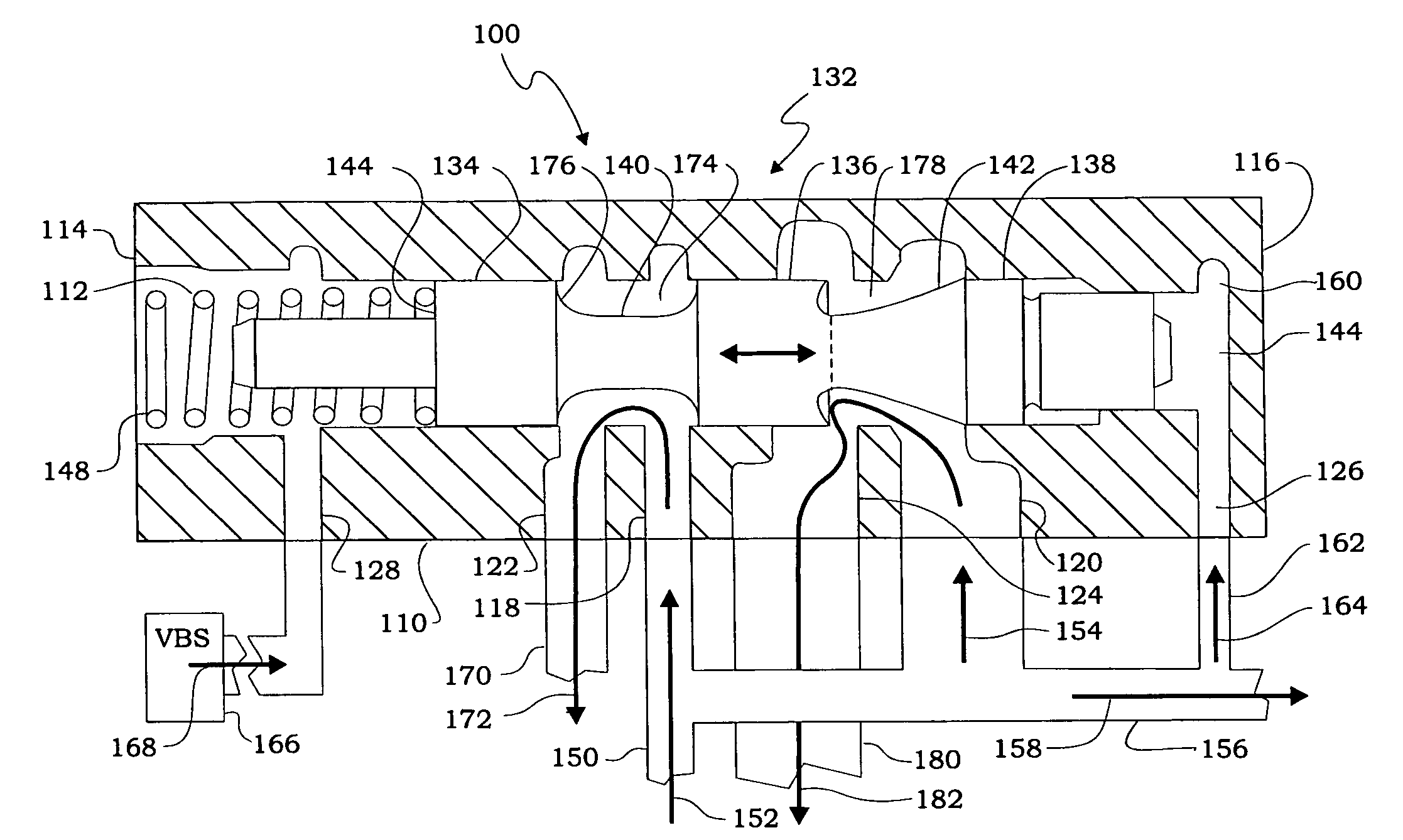
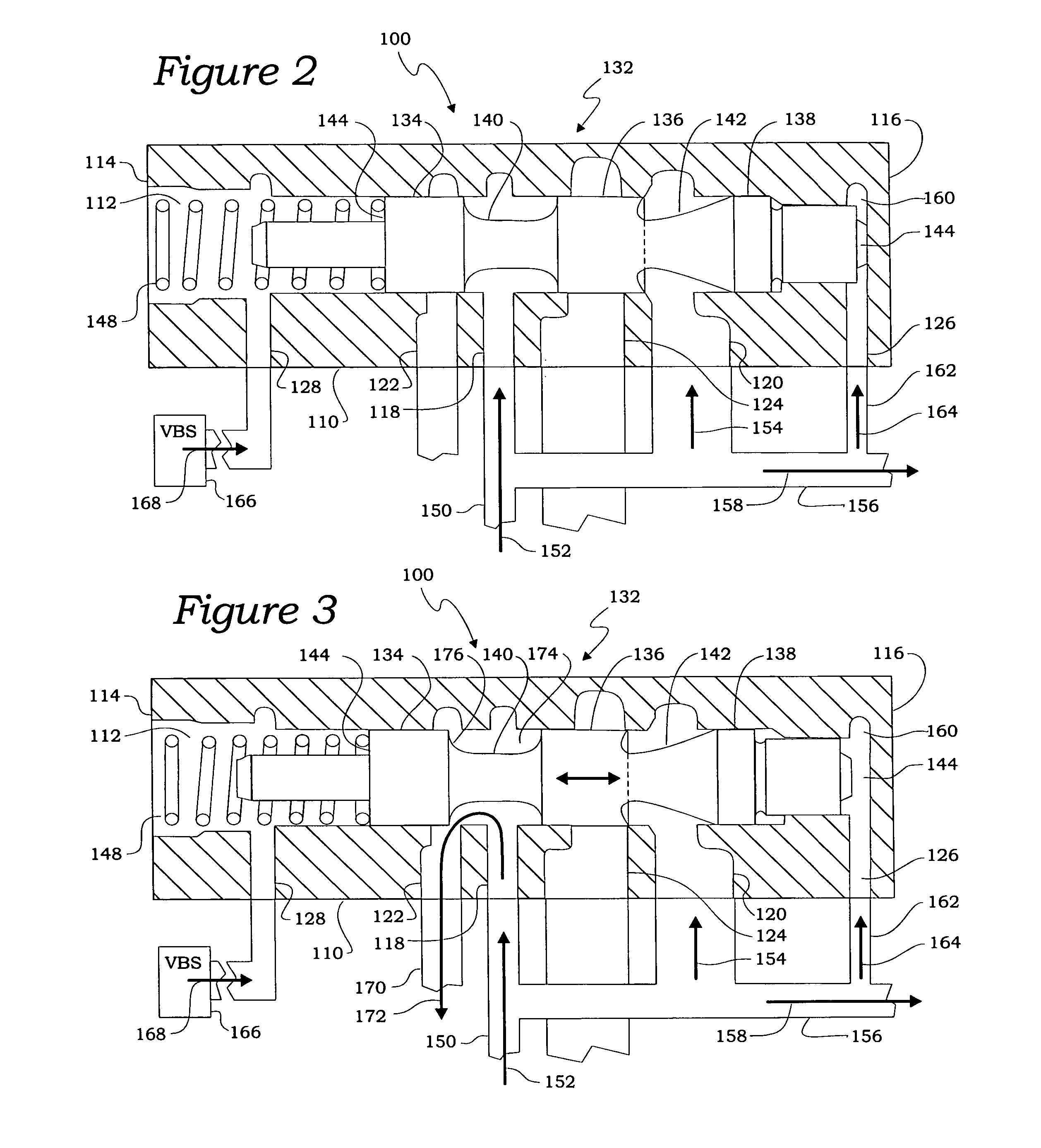
[0030]The present invention relates, generally, to an automatic transmission for a motor vehicle that includes a pressure regulator, and more specifically to an automatic transmission having a pressure regulator with flow force compensation. Generally speaking, an automatic transmission forms a portion of a vehicle powertrain and is responsible for taking a torque input from a prime mover, such as an internal combustion engine, and transmitting the torque through selectable gear ratios to the vehicle drive wheels. With regard to the recent evolution in vehicle transmissions that have produced automatic transmissions of the types generally known as automated manual transmissions and dual clutch transmissions, the present invention overcomes the shortcomings and drawbacks related to employing a transmission pressure regulator that does not provide compensation for the flow forces that inherently act upon the valve member of the regulator.

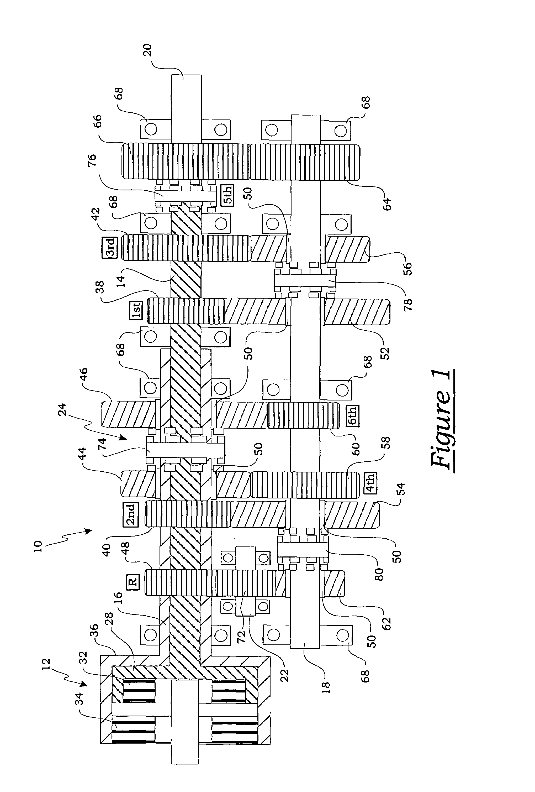
[0031]One example of an automatic transmission...


PUM


Abstract

An automatic transmission having a pressure regulator with flow force compensation. The pressure regulator includes a valve body having a valve bore and at least one inlet and at least one outlet adapted to provide fluid communication with a source of pressurized hydraulic fluid and a return to the source of pressure. A valve member is slidingly disposed within the valve body that includes at least one valve element having an outer diameter and a metering face. The metering face is adapted to control the flow of pressurized hydraulic fluid between the inlet and the outlet of the valve body. The metering face includes a flow force compensating annular void disposed adjacent to the outer diameter that is defined by a lead angle α measured between the outer surface and a line intersecting the outer surface and tangential to the annular void.

Description

BACKGROUND OF THE INVENTION[0001]1. Field of the Invention[0002]The present invention relates, generally to an automatic transmission having a pressure regulator and, more specifically, to an automatic transmission having a pressure regulator with flow force compensation.[0003]2. Description of the Related Art[0004]Generally speaking, land vehicles require a powertrain consisting of three basic components. These components include a power plant (such as an internal combustion engine), a power transmission, and wheels. The power transmission component is typically referred to simply as the “transmission.” Engine torque and speed are converted in the transmission in accordance with the tractive-power demand of the vehicle. Presently, there are two typical transmissions widely available for use in conventional motor vehicles. The first and oldest type is the manually operated transmission. These transmissions include a foot-operated start-up or launch clutch that engages and disengages...

Claims


Application Information

Patent Timeline
Patent Type & Authority Patents(United States)
IPC IPC(8): G05D7/01
CPCF16H61/0021F16H2061/0253F16H2061/0037Y10T137/2652Y10T137/8671Y10T137/87249F16H61/00
Inventor XIANG, XIAONINGKOENIG, MELISSAVUKOVICH, WILLIAM
Owner BORGWARNER INC
Why Eureka
Try Eureka