Belt junction conveyor

a belt junction and conveyor technology, applied in the field of conveyors, can solve the problems of increasing the possibility of belt removal or meandering, reducing the running resistance, and reducing the effectiveness of aimed meandering prevention, so as to reduce the noise, reduce the meandering and vibration of the belt, and suppress the movement of vibration or ruffl

Inactive Publication Date: 2008-10-07
SANKI ENG CO LTD
View PDF18 Cites 5 Cited by
  • Summary
  • Abstract
  • Description
  • Claims
  • Application Information

AI Technical Summary

Benefits of technology

[0011]The change of direction by merely rewinding a belt by a split roller will allow the roller to cause rolling friction, which reduces the running resistance compared with the sliding friction of a non-rotator. However, a traveling belt will slide toward a position having less resistance along with the inclination of a rewinding part, which increases the possibility of belt removal or meandering. Furthermore, if a pair of upper and lower inclined rollers are used in such a manner that an engaging concave is provided on rollers and a stopper is provided on both sides of a belt, the belt stopper comes in contact with the inclined rollers slantingly, which causes the engaging concave at the roller side to become a wide groove. Therefore, because of the degree of freedom of the stopper movement, the effectiveness of aimed meandering prevention is small.
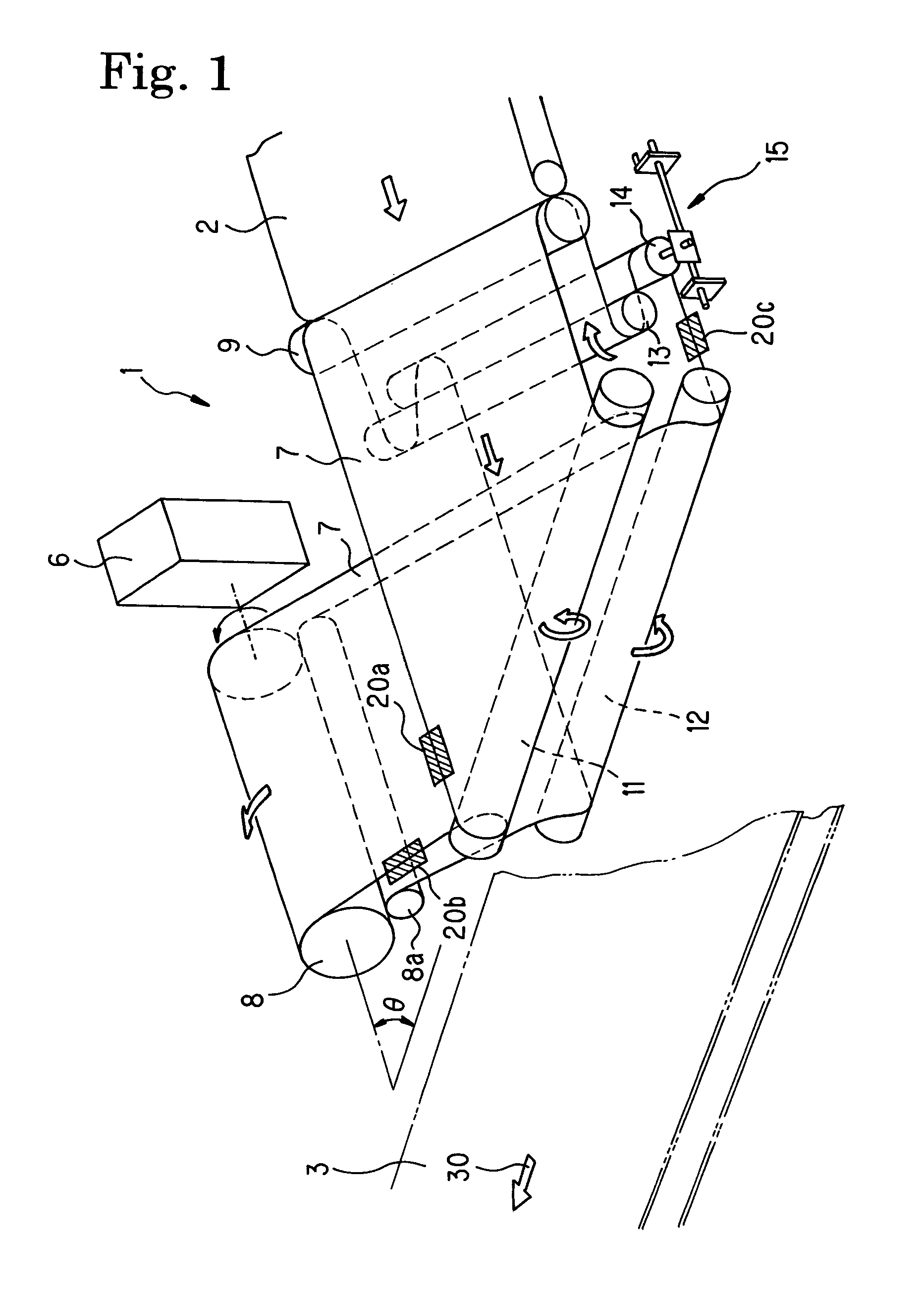
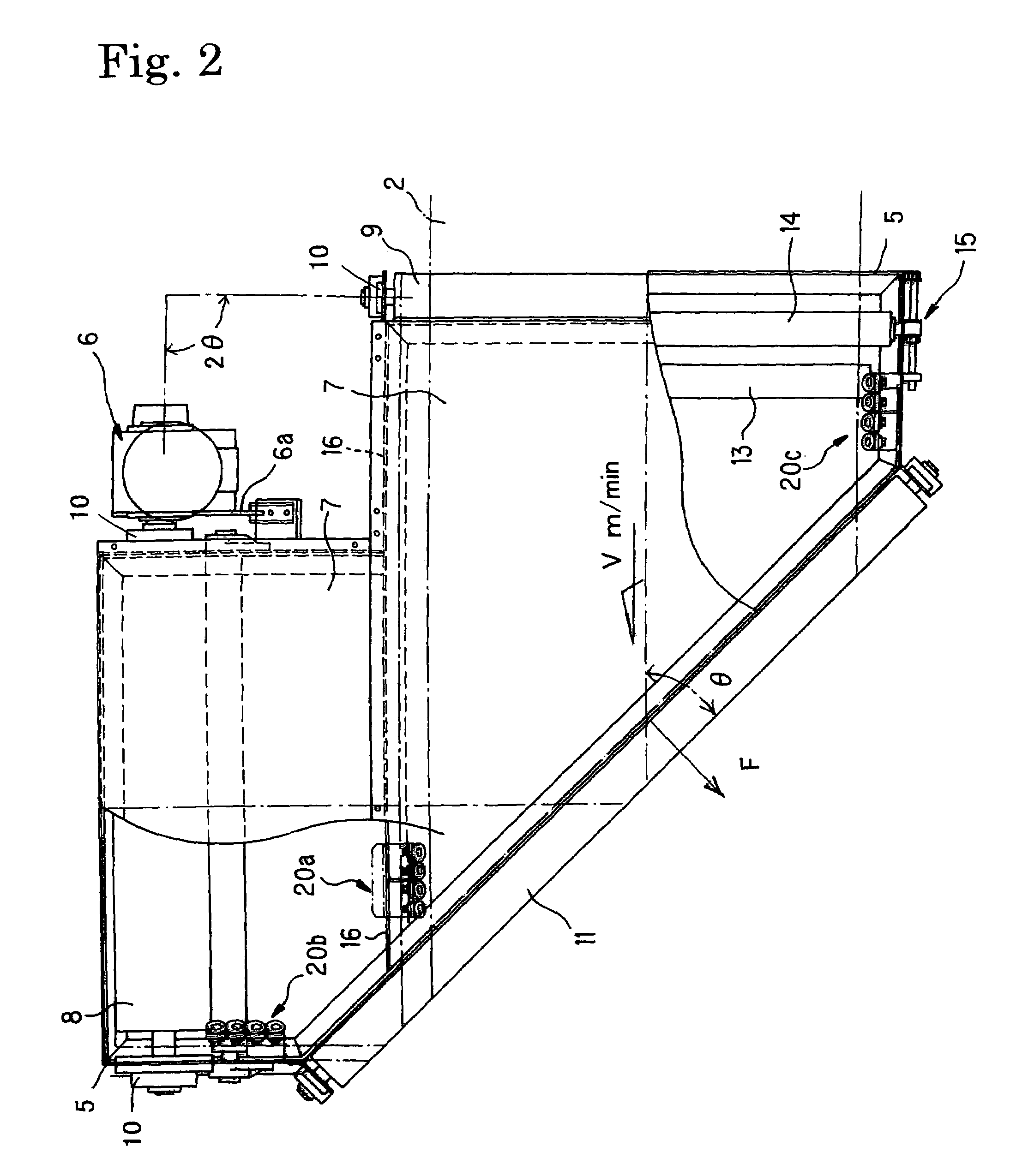
[0012]Then, it is expected to provide a system in which junction reminding part is formed as a rotator (upper and lower inclined pulleys) so that running load is reduced, as well as the decrease of motor capacity, vibration, and noise are suppressed. In addition, in such a system, a belt meandering, which is easily capable of happening at a rewinding part in an inclined roller system, is suppressed, and maintenance workability is greatly improved.
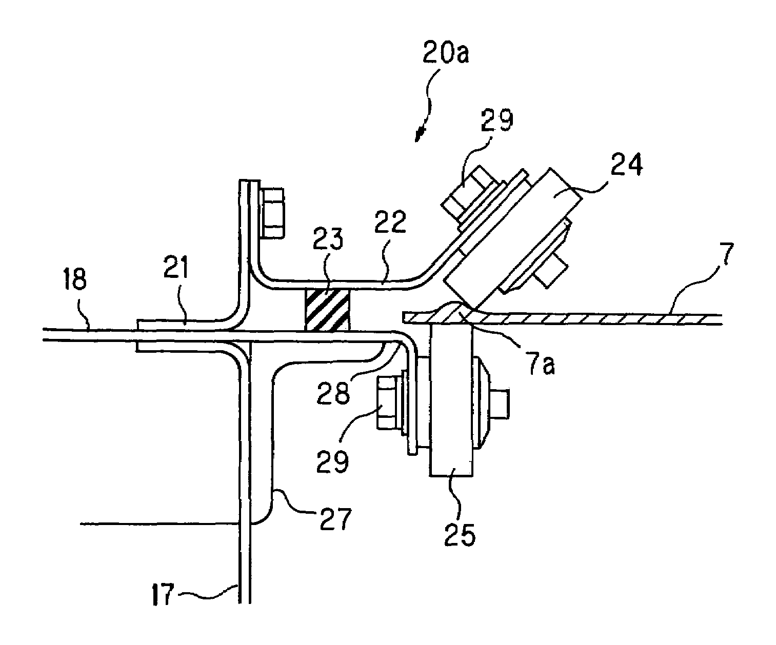
[0013]The object of the invention is to provide a belt junction conveyor comprising a holder unit which is elastically holding a profile (semicircular convex or a thick edge part having a round shape) of a belt arranged in proximity to an edge of a traveling belt to suppress remaining tendency of direct advance of the belt when it is rewound by the upper and lower inclined pulleys, so that the bias due to the belt rewinding is suppressed, which allows the belt to advance smoothly.
[0014]An object of the present invention is to provide a belt junction conveyor in which a junction belt is disposed in an inclined manner to have a predetermined degree of 90 or less to a confluence of a carrier line when viewed from the plane, in which a pair of upper and lower inclined pulleys are arranged adjacent to the above disposed part, and both end pulleys are mounted on a position in such a manner to have a distance from each other to sustain a double angle of the above predetermined angle at the disposed side so that the advancing side belt and returning side belt are rewound by the upper and lower inclined pulleys, respectively, so as to travel toward each of the above end pulleys, said belt junction conveyor comprising a semicircular convex part or a roundish thick periphery formed at both edges of a belt front surface or a back surface; and a holder unit arranged at several locations adjacent to the edge of the traveling belt in such a manner to elastically come into contact with the above semicircular convex part or the thick periphery so as to suppress the meandering tendency resulting from rewinding a belt.
[0017]As explained above, in a belt junction conveyor of the present invention a rollback part is formed as an upper and lower inclined pulleys having a predetermined angle to a carrier line, and a holder unit controls a belt profile that is a semicircular convex part or a roundish thick periphery, so that the traveling load is reduced and, therefore, motor capacity is decreased (for example, 4.8 A according to the inventive compared with 12.0 A in a conventional type, which results in 40% decrease). Furthermore, a holder unit suppresses vibration or ruffle movement in the belt cross direction resulting when a belt is rewound by an inclined pulley that is a rotator. Thereby, the belt junction conveyor of the invention reduces meandering and vibration of a belt, or noise. In addition, since a holder unit is formed as a wheel for pressing a convex part of a belt (spring guide wheel), a belt is supported by a fixed suppressing force, so that a belt can travel correcting bias due to the belt rewinding, and eliminating possible belt damage.
[0019]As explained previously, since a belt rewinding part is formed with a rotator (upper and lower inclined pulleys), it is possible to reduce the traveling load, to decrease a motor capacity, to suppress vibration and noise. In addition, since an edge (a semicircular convex part or a roundish thick periphery) of a belt controlled by a holder (a guide holder), a belt meandering more frequently happening in an inclined roller system compared with a conventional belt rewinding part using a slide guide is effectively suppressed, so that the maintenance performance is greatly improved.

Problems solved by technology

The change of direction by merely rewinding a belt by a split roller will allow the roller to cause rolling friction, which reduces the running resistance compared with the sliding friction of a non-rotator.
However, a traveling belt will slide toward a position having less resistance along with the inclination of a rewinding part, which increases the possibility of belt removal or meandering.
Therefore, because of the degree of freedom of the stopper movement, the effectiveness of aimed meandering prevention is small.

Method used


Image

  • Belt junction conveyor
  • Belt junction conveyor
  • Belt junction conveyor

Examples


Embodiment Construction

[0029]Hereinafter, the preferred embodiments of the invention are explained by referring to drawings. FIG. 1 is a schematic perspective view of a belt junction conveyor 1 of the present invention. A junction belt 7 (hereinafter, referred to a resin belt or a belt) is disposed in an inclined manner to have a predetermined degree of 90 or less to a confluence of a carrier line 3 when viewed from the plane, in which a pair of upper and lower inclined pulleys 11, 12 are arranged adjacent to the disposed part, and both end pulleys 8, 9 are mounted on a position where a double angle of the predetermined angle is maintained while keeping a distance from each other at the disposed side, so that each advancing side belt and returning side belt 7 is rewound by the upper and lower inclined pulleys 11, 12 to travel toward each of the end pulleys 8, 9. In this embodiment, a disposed angle is θ=45° so that both end pulleys 8, 9 are 2θ=90°, that is, the end pulleys 8, 9 are arranged at a position ...


PUM


Abstract

A belt junction belt conveyor in which a thick periphery edge of a belt is elastically held after the belt is rewound by upper and lower inclined pulleys so that the meandering tendency of the belt occurring from being rewound by the upper and lower inclined pulleys is effectively prevented.

Description

BACKGROUND OF THE INVENTION[0001]1. Field of the Invention[0002]The present invention relates to a conveyor used for converging carrier object to a conveyor line, and more particularly, to a belt junction conveyor in which a returning belt is prevented from moving toward the direction of a bias angle due to inclined pulleys mounted on an upper side and a lower side.[0003]2. Prior Art[0004]A belt junction conveyor (converging conveyor) provided at a confluence of a transportation line is disposed to a conveyor line obliquely (45 degrees), and a rewinding part (or a returning part) of a converging side belt is mounted on the disposed part. In a known prior art, a belt is advanced by providing the upper side and the lower side of a rewinding part with a guide body made of aluminum sheet (for example, Patent Document 1). In another prior art, in order to prevent a belt from meandering, a sliding strip is employed (for example, Patent Documents 2 and 3). Or, in another prior art, a narro...

Claims


Application Information

Patent Timeline
Patent Type & Authority Patents(United States)
IPC IPC(8): B65G21/16B65G15/60B65G15/28
CPCB65G15/60
Inventor HISHINUMA, NOBUYA
Owner SANKI ENG CO LTD
Why Eureka
Try Eureka