
Aerosol spray masking device

a technology of spray masking device and spray mask, which is applied in the direction of lighting and heating apparatus, combustion types, transportation and packaging, etc., can solve the problems of troublesome phenomenon, lack of viewing window or pressure release vent, etc., and achieve the effect of preventing overspray

Active Publication Date: 2008-10-07
MONTERROSA CHRISTOPHER H
View PDF19 Cites 17 Cited by
  • Summary
  • Abstract
  • Description
  • Claims
  • Application Information

AI Technical Summary

Benefits of technology

"The present invention is a masking device that prevents over-spray when using an aerosol can to apply paint, stains or finishes to a work surface. It can also be used to apply any aerosolized product to a surface, such as herbicides or insecticides to a specific area, or to apply disinfectants to a surface to be sterilized such as the dermis of a surgical patient. The masking device has a horizontal channel structure with an aperture for inserting an aerosol nozzle, and a small orifice for containing the aerosol. It has a front, back, interior surface and exterior surface, with a planar opening at the front and top, and a bottom with a raised bead to prevent material from excess aerosol droplets from transferring to the work surface. The masking device also has raised product accumulators and slits to prevent aerosol pressure build up and collect excess material from over-spray."

Problems solved by technology

A troubling phenomenon associated with aerosolized products from these families is “over-spray”.
However, it does not include a viewing window or a pressure release vent.

Method used


Image

  • Aerosol spray masking device
  • Aerosol spray masking device
  • Aerosol spray masking device

Examples


Embodiment Construction

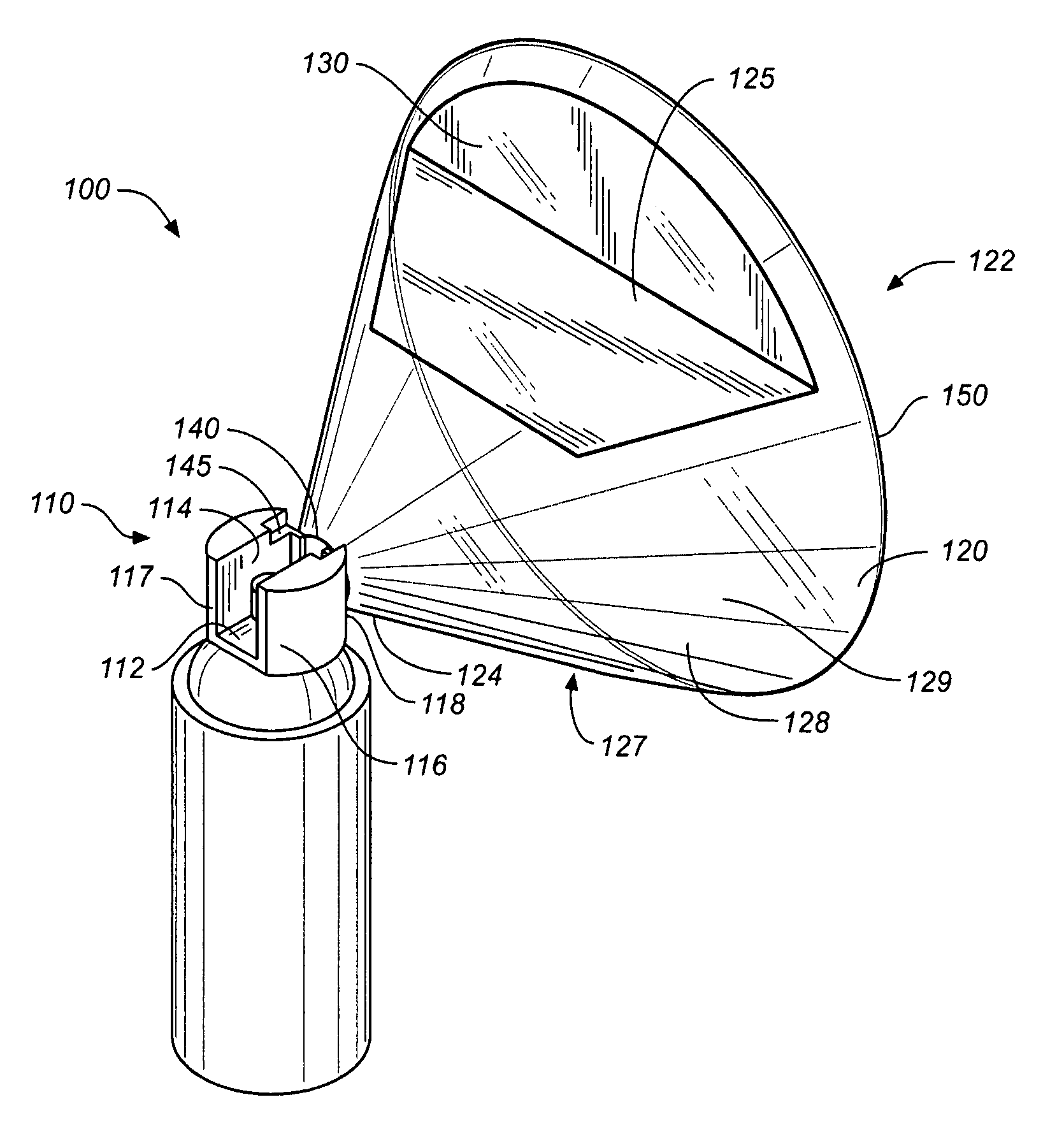
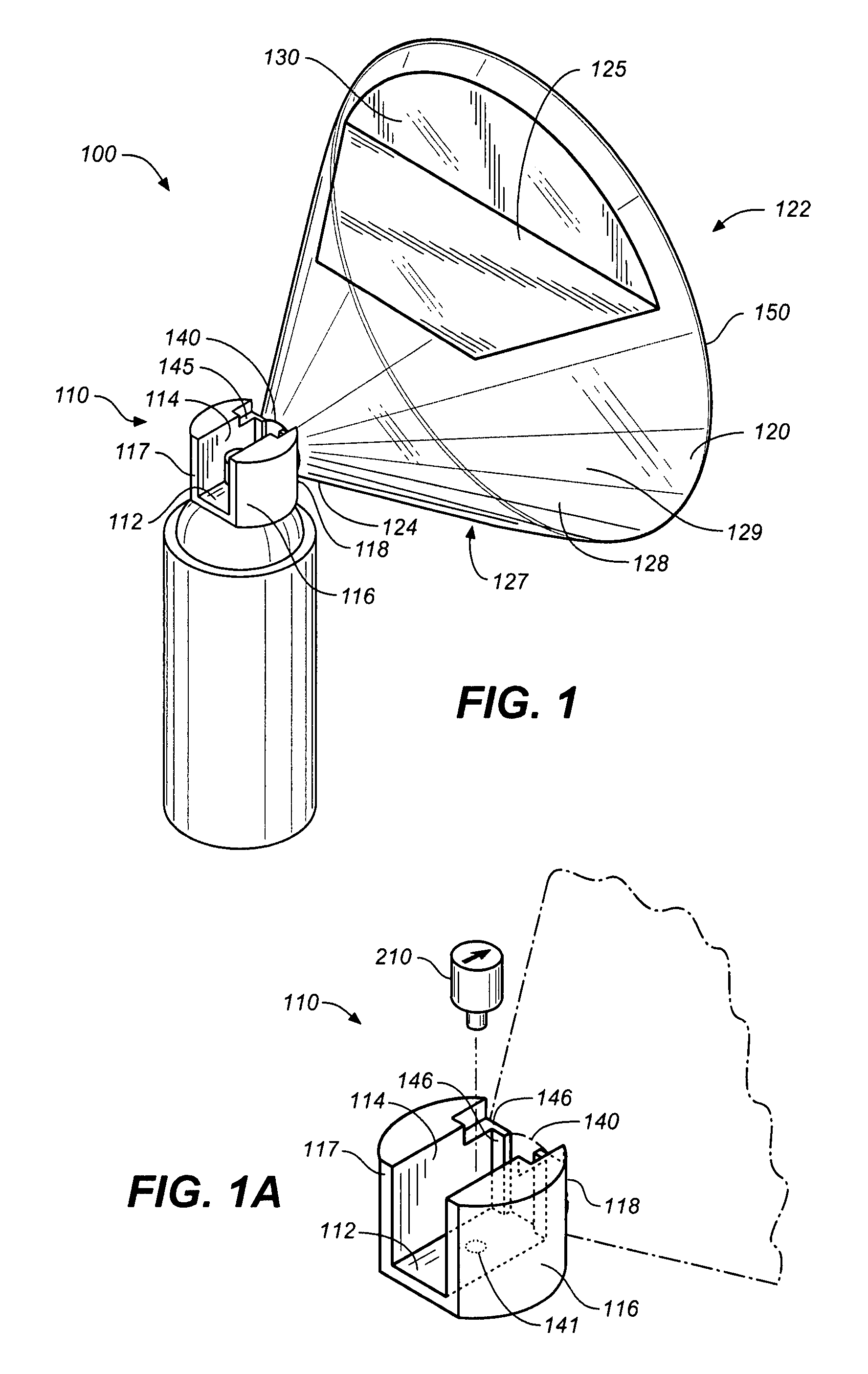
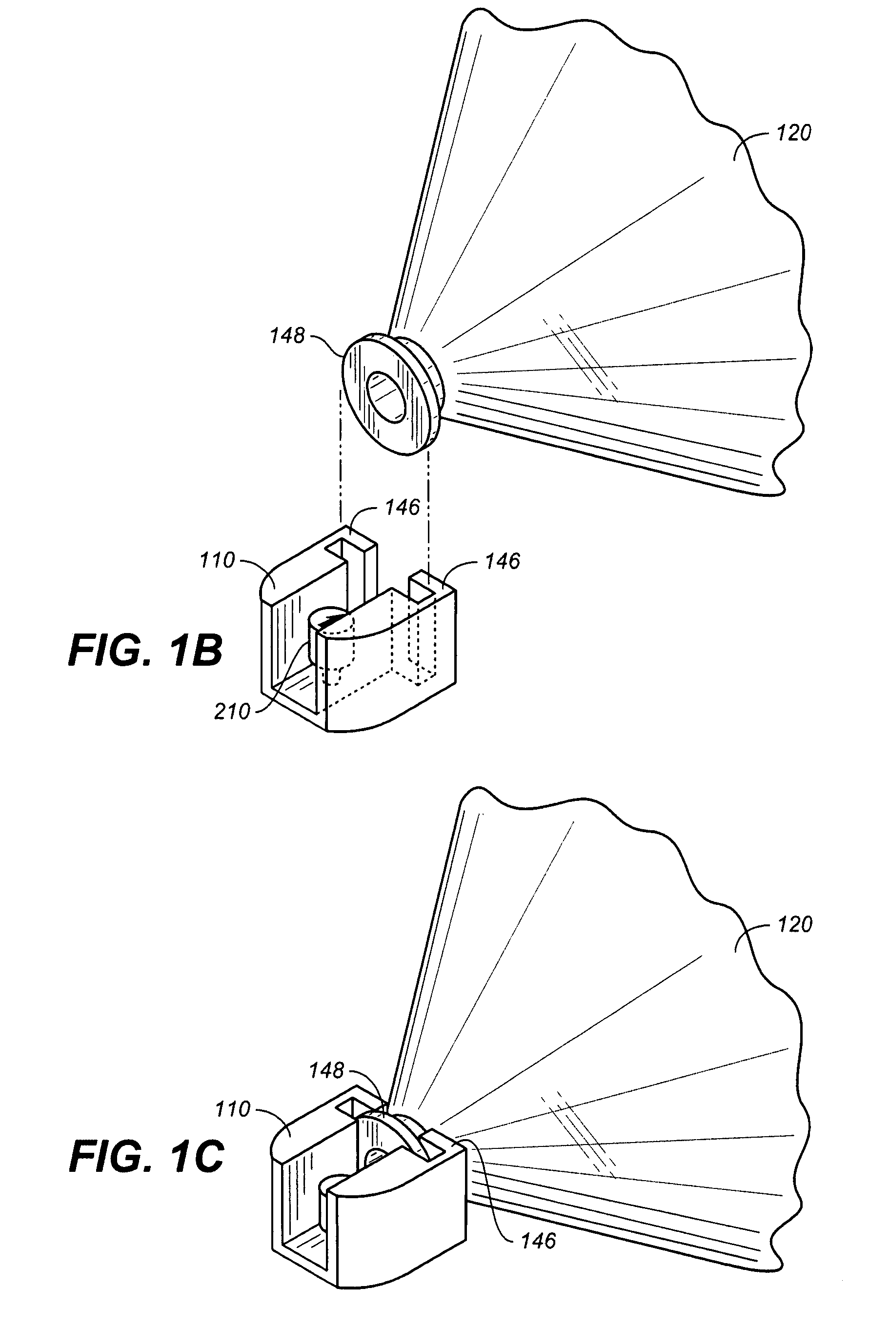
[0053]Referring to FIGS. 1 through 4, wherein like reference numerals refer to like components in the various views, there is illustrated therein a new and improved aerosol spray masking device, generally denominated 100 herein.

[0054]FIG. 1 illustrates a preferred embodiment of the aerosol spray masking device 100, comprising a horizontal channel 110, having a horizontal channel bottom 112, a horizontal channel left side 114 and a horizontal channel right side 116, a horizontal channel back end 117 and a horizontal channel front end 118. A masking unit 120 having a masking unit front 122 and a masking unit back 124, a small orifice 140 and a large orifice 150 which share an axis, and masking unit top 126 and a masking unit bottom 127, and an interior surface 128 and an exterior surface 129. Also depicted is an observation cut-out 125 with a replaceable transparent film 130 that is utilized as a viewing port to observe the progress of work being performed. An attachment means 145 for...


PUM


Abstract

A masking device to prevent over-spray when using an aerosol can to apply aerosols to a work surface. The device includes a horizontal channel structure, the back end of which is essentially open and serves as an insertion point for an aerosol nozzle feed tube from an aerosol can, while the front end serves as an attachment seat for a masking unit. The back end of the horizontal channel is open, providing the user access to the aerosol nozzle in order to actuate the aerosol nozzle with a finger, whereby an aerosol is propelled forward into a masking unit. The masking unit has a small orifice creating a planar opening at the back, and a large orifice creating a generally planar opening at the front The masking unit is essentially hollow, providing the ability to contain an aerosol, the large orifice serving as a mask against a target surface. The masking unit has an observation cut out covered with a transparent film, a vent to exhaust excess pressure and aerosol, and raised beads radiating from the small orifice to the large orifice, which serve as excess aerosol accumulators.

Description

CROSS REFERENCE TO RELATED APPLICATIONS[0001]The present application is a continuation-in-part patent of U.S. patent application Ser. No. 11 / 421,736 filed Jun. 1, 2006 (now abandoned), which claims the benefit of the filing date of U.S. Provisional Patent Application Ser. No. 60 / 687,238, filed Jun. 3, 2005.STATEMENT REGARDING FEDERALLY SPONSORED RESEARCH OR DEVELOPMENT[0002]Not applicable.REFERENCE TO A MICROFICHE APPENDIX[0003]Not applicable.TECHNICAL FIELD[0004]The present invention relates generally to spray masking devices, more particularly to spray masking devices that prevent over-spray phenomenons associated with aerosolized paints, pigments, stains, varnishes and other materials applied by the use of propellants to create an aerosol.BACKGROUND INFORMATION AND DISCUSSION OF RELATED ART[0005]Aerosolized pigments, paints and varnishes have been in use for many years. A troubling phenomenon associated with aerosolized products from these families is “over-spray”. Generally, whe...

Claims


Application Information

Patent Timeline
Patent Type & Authority Patents(United States)
IPC IPC(8): B05B1/28B05B1/26B05B15/04B05B7/32B65D83/14B65D83/28
CPCB65D83/30B05B12/24
Inventor MONTERROSA, CHRISTOPHER H.
Owner MONTERROSA CHRISTOPHER H
Learn More