
Method of preparing turbine blades for spray coating and mounting for fixing such a turbine blade

a technology of spray coating and turbine blades, which is applied in the direction of superimposed coating process, liquid/solution decomposition chemical coating, manufacturing tools, etc., can solve the problems of time-consuming and costly addition of methods, and the mounting of spray coating apparatus described above is not suitable for coating the entire surface area of the blade region

Inactive Publication Date: 2010-05-18
SIEMENS AG
View PDF10 Cites 2 Cited by
  • Summary
  • Abstract
  • Description
  • Claims
  • Application Information

AI Technical Summary

Benefits of technology

This solution effectively prevents overspray on uncoated areas, eliminates the need for grinding, and enhances cooling efficiency by sealing the gap, reducing material flaking during removal.

Problems solved by technology

This additional method step is time-consuming and costly.
The mounting for the spray coating apparatus described above is not suitable for coating the entire surface area of the blade region of a turbine blade, since a considerable part of the blade region is covered by the mounting itself.

Method used


Image

  • Method of preparing turbine blades for spray coating and mounting for fixing such a turbine blade
  • Method of preparing turbine blades for spray coating and mounting for fixing such a turbine blade
  • Method of preparing turbine blades for spray coating and mounting for fixing such a turbine blade

Examples


Embodiment Construction

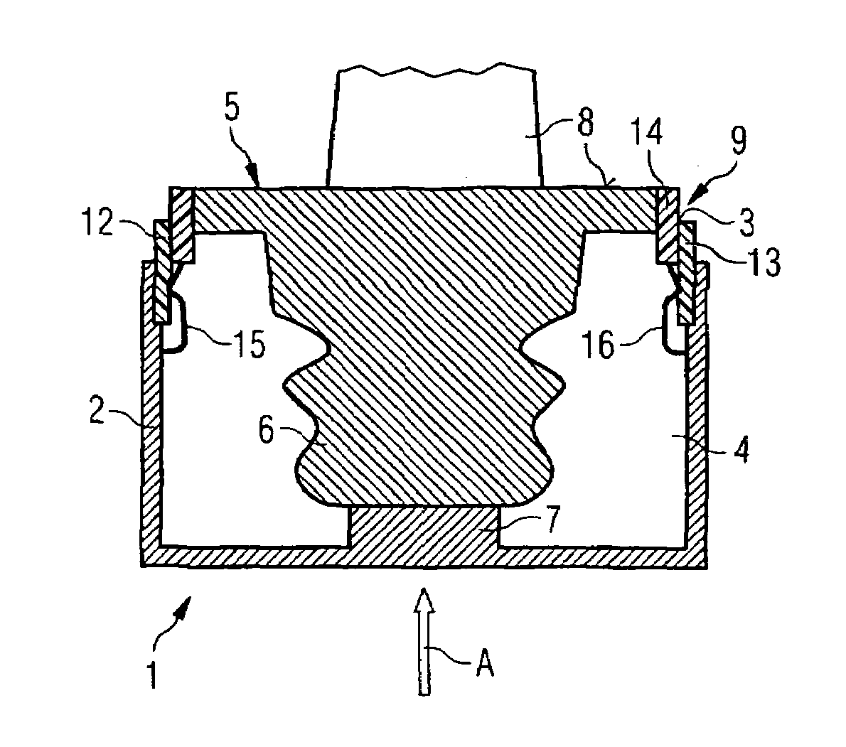
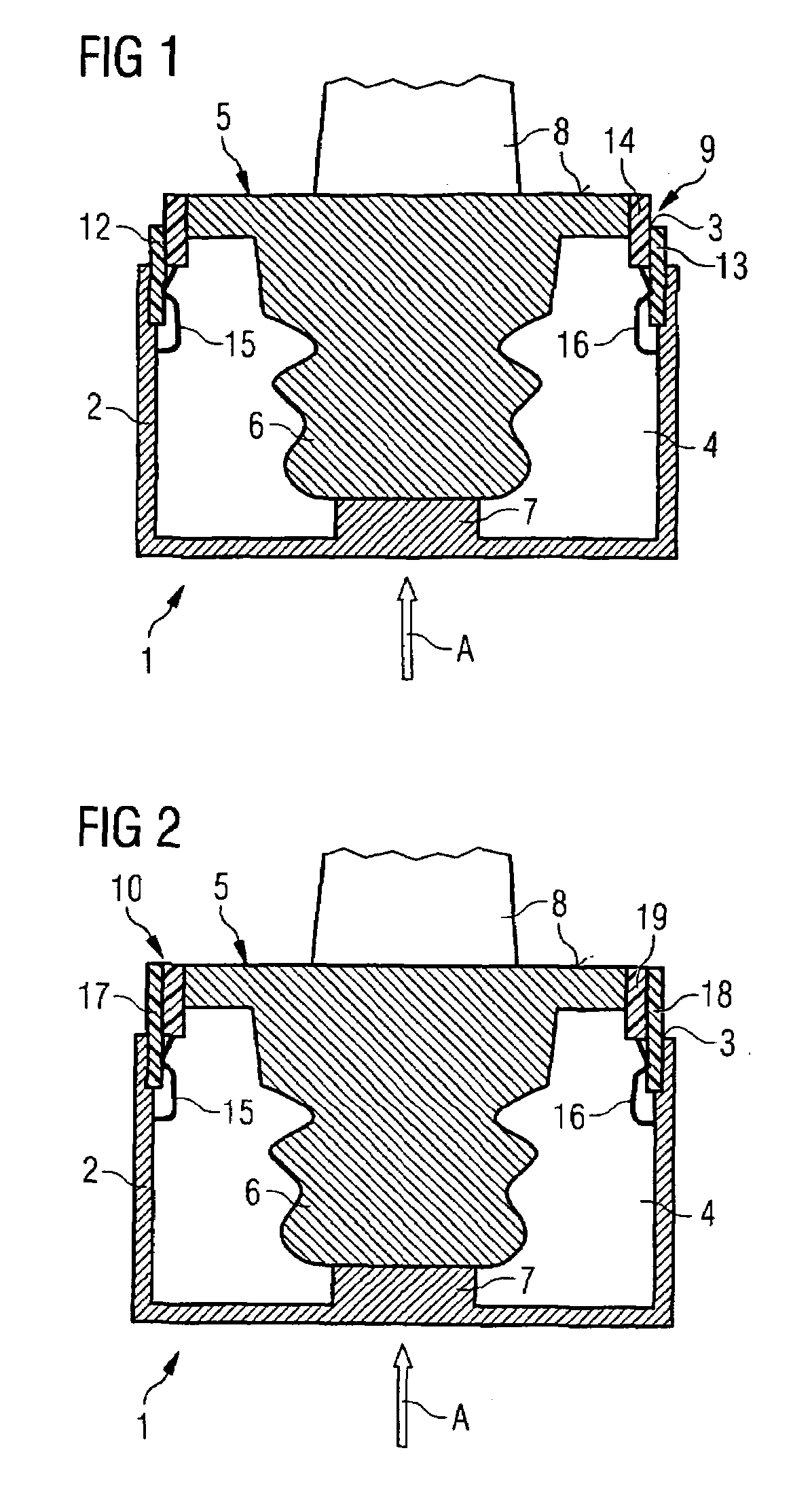
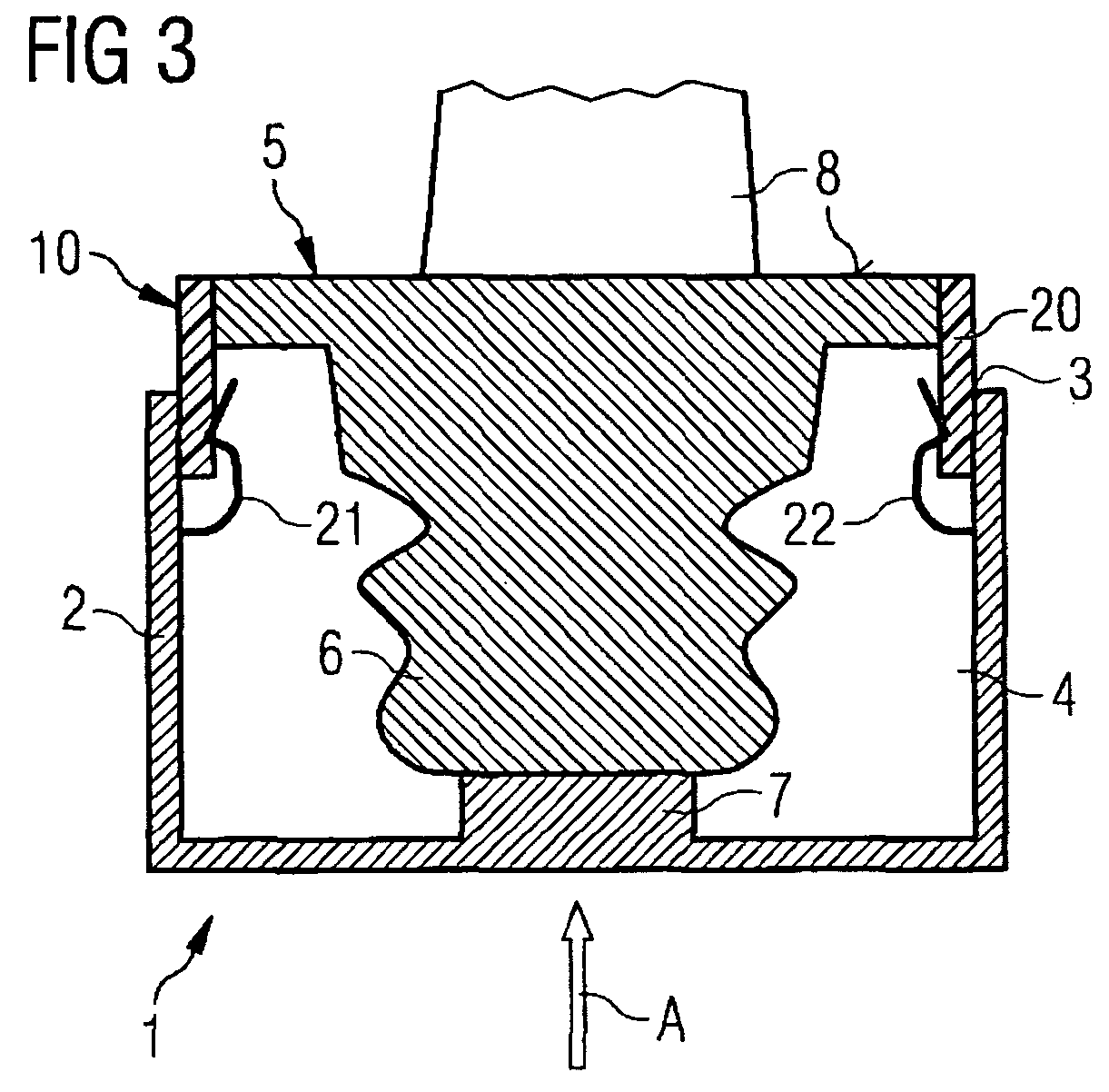
[0020]The mountings 1 represented in FIGS. 1 to 3 have in each case a pot-like hollow body 2, which has on the upper side an opening bounded by a rim 3 of the opening. The hollow body 2 encloses a cavity 4, into which a turbine blade 5 is inserted vertically from above in such a way that its blade root 6 is located substantially within the cavity 4 and rests there at the end face on a base 7, while the turbine blade 5 extends with its blade region 8 that is subjected to the medium flowing through during the operation of the turbine provided with it outside the mounting 1. Said region is represented in a shortened form. It is indicated by the arrow A that the turbine blade 5 is cooled with compressed air during the coating operation.

[0021]The mounting 1 is intended for being inserted into a spray coating apparatus, in order that the blade region 8—also including the upper side of the blade root 6—is provided there with a metal coating, which is applied by means of plasma spraying. In...


PUM

PropertyMeasurementUnit
shieldingaaaaaaaaaa
flexibleaaaaaaaaaa
adhesive resistantaaaaaaaaaa

Abstract

The invention relates to a method of preparing turbine blades for spray coating their blade region that is subjected to the medium flowing through during operation in a spray coating apparatus, in which the turbine blade is inserted with its blade root into a cavity of a mounting in such a way that it protrudes with the blade region that adjoins the blade root from an opening of the cavity to form a gap between the rim of the opening and the turbine blade, and in which the gap is bridged by a shielding fixed on the mounting, which is characterized in that a shielding layer of a plastic which is resistant during the spray coating is used for the shielding, the shielding layer being arranged in such a way that it reaches up to the boundary between the blade root and the blade region.

Description

CROSS REFERENCE TO RELATED APPLICATIONS[0001]This application claims the benefits of European Patent application No. 05019698.9 filed Sep. 9, 2005 and is incorporated by reference herein in its entirety.FIELD OF THE INVENTION[0002]The invention relates to a method of preparing turbine blades for spray coating their blade region that is subjected to the medium flowing through during operation in a spray coating apparatus, in which the turbine blade is inserted with its blade root into a cavity of a mounting in such a way that it protrudes with the blade region that adjoins the blade root from an opening of the cavity to form a gap between the rim of the opening and the turbine blade, and in which the gap is bridged by a shielding fixed on the mounting. The invention also relates to a mounting for fixing a turbine blade in a spray coating apparatus, with at least one cavity having an opening for receiving the turbine blade in such a way that the turbine blade is inserted with a blade ...

Claims


Application Information

Patent Timeline
Patent Type & Authority Patents(United States)
IPC IPC(8): B05C21/00B05B12/20
CPCC23C4/005B05B15/045B05B12/20C23C4/01
Inventor BECK, THOMASLADRU, FRANCIS-JURJENLIPPKE, BENJAMINMENSING, MARCUS
Owner SIEMENS AG
Learn More