Window vent stop

a window and stop technology, applied in the direction of wing accessories, carpet fasteners, mechanical devices, etc., can solve the problems of double hung windows that are opened wide, unauthorized ingress and egress from the premises, and the side of the fully opened position,

Inactive Publication Date: 2008-10-07
VISION INDS GROUP
View PDF21 Cites 27 Cited by
  • Summary
  • Abstract
  • Description
  • Claims
  • Application Information

AI Technical Summary

Benefits of technology

[0010]It is an object of the present invention to provide a vent stop that operates more easily than the prior art vent stops.
[0011]It is an object of the present invention to provide an improved vent stop that is more dependable in its operation than the prior art vent stops.
[0012]It is an object of the present invention to provide a vent stop that provides a mechanism that permits the tumbler to be retained in a recessed position more readily than the prior art vent stops.
[0013]It is still another object of the present invention to provide a vent stop that is more readily placed in a locking position by a user without having to shift the tumbler away from the catch portion of the housing.

Problems solved by technology

While a fully opened position can be desirable for ventilation purposes there can be a downside to the fully opened position.
One downside is security.
A fully open window or door, however, can be a location for unauthorized ingress and egress from the premises.
For example, a double hung window that is opened wide can be a source of danger to small children who may climb up to the window.
One of the problems in the operation of the prior art sash locks is that it is frequently difficult for the user to move the tumbler away from the housing to release the tumbler from its recessed position.
Many times, the user finds it difficult to maneuver the tumbler away from the housing to release the tumbler.
Although many tumblers are provided with surfaces that increase the user's ability to move the tumbler, these surfaces are frequently insufficient to overcome the difficulties of the prior art vent locks.
Similarly, the prior art sash locks can also be difficult to operate when the user wants to release the window or door for travel.

Method used


Image

  • Window vent stop
  • Window vent stop
  • Window vent stop

Examples


Embodiment Construction

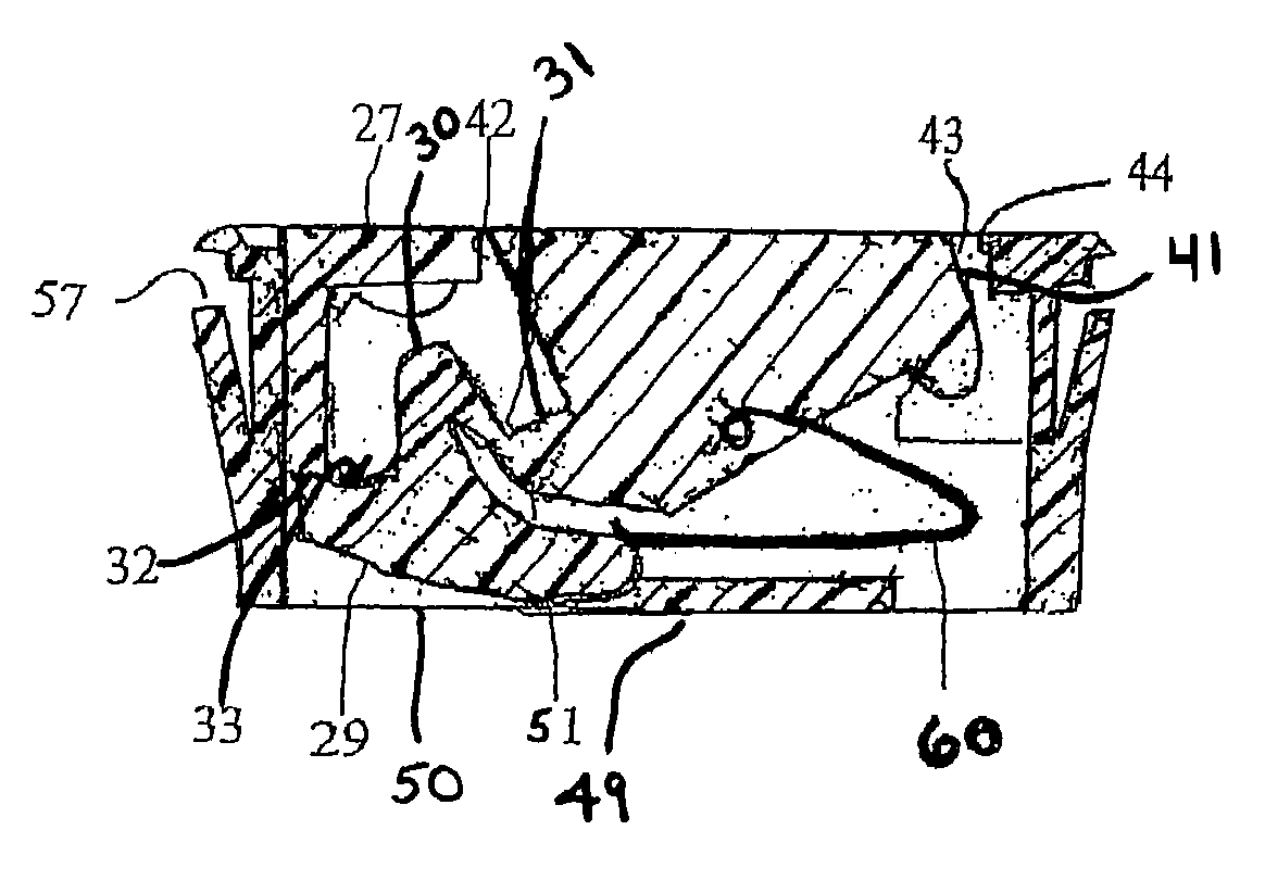
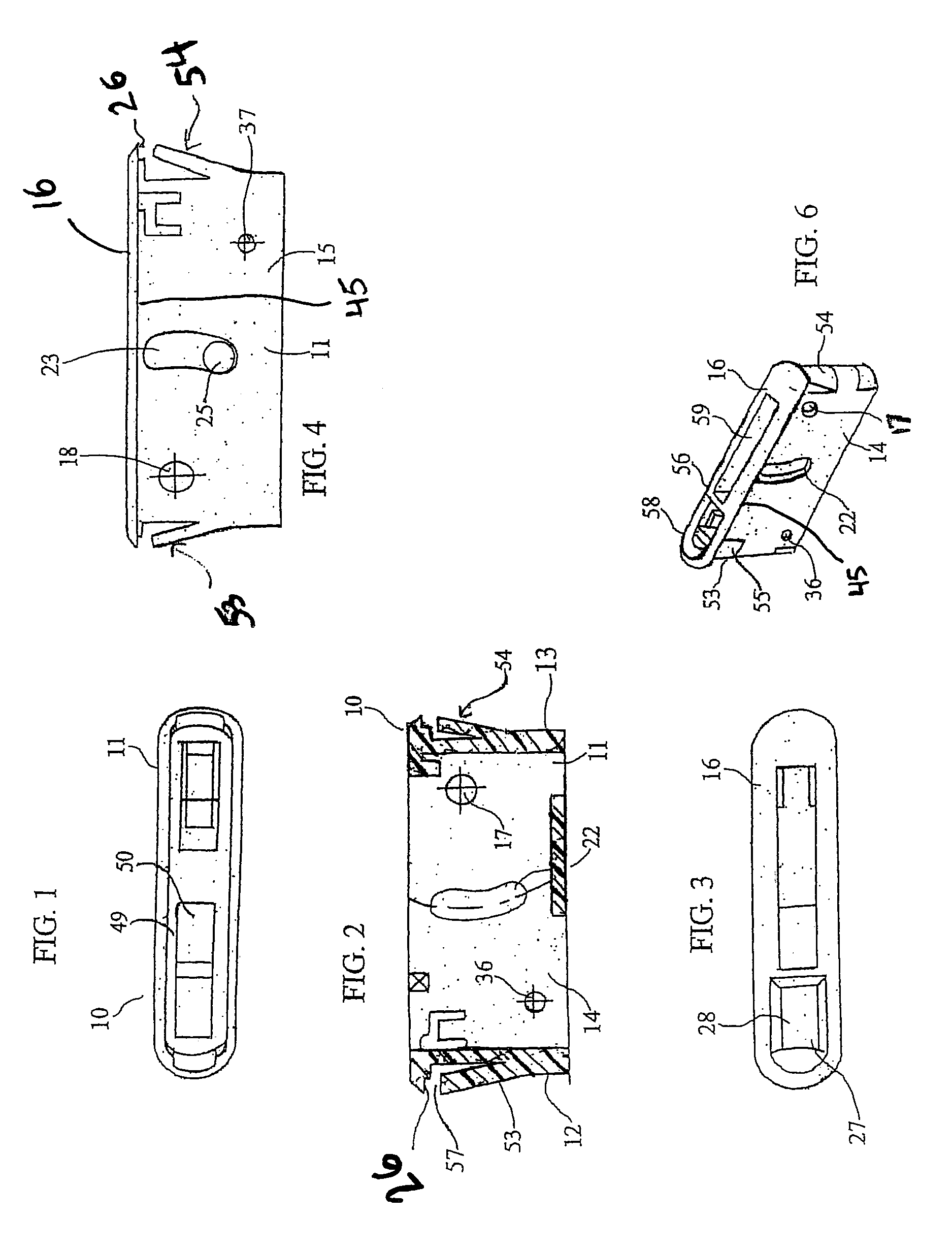
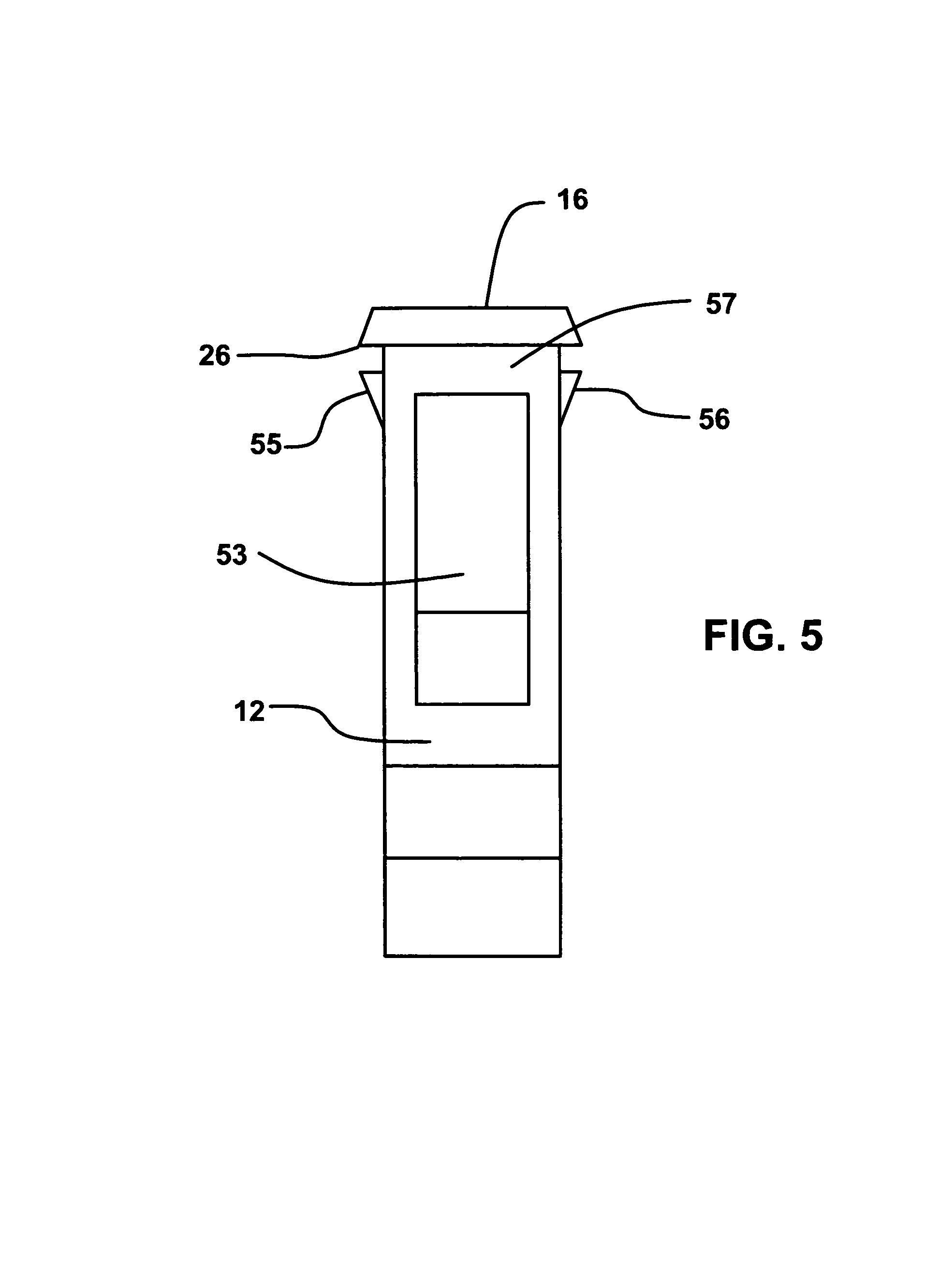
[0051]The window or door assembly that may employ the vent stop of the present invention may be a conventional double hung window, a single hung window, sliding window, sliding door and the like. For convenience the present invention will be described with reference to a double hung window but the same applies to each of the above other types of windows and doors having at least one sliding member. The double hung window usually includes upper and lower sash window frames, that are provided with suitable glazing to protect and bed the glass. The sashes are conventionally mounted within a main jamb frame for vertical reciprocal sliding movement therein. Sliding windows and doors are mounted for horizontal reciprocal sliding. Both the jamb frame and the sashes can be formed of different materials, such as metal or strong and rigid plastics well known in this field. The sashes are preferably fabricated from elongate framing members of hollow configuration and are generally rectangular ...


PUM


Abstract

A window vent stop for use in a sliding sash window assembly or a sliding door assembly. The vent stop has a housing adapted to be disposed in a recess in a non-movable sash member. This housing includes a cavity with a bottom plate therein. A tumbler has at least one pivot for pivotally securing the tumbler to the housing for movement between an extended position, to prevent movement of the sliding sash member and a retracted position, to allow movement of the sliding sash member. Also within the housing is a spring for biasing the tumbler toward the extended position. The tumbler has a first locking member that contacts a second locking member on a release member when the tumbler is in the retracted position and the first locking member does not contact the second locking member when the tumbler is in the extended position.

Description

FIELD OF THE INVENTION[0001]The present invention relates to improved window vent stops particularly for double hung windows and the like and to improvements in their operation. These window vent stops are used to prevent a window or door from opening more than a desired amount.BACKGROUND OF THE INVENTION[0002]There are a number of different types of window vent stops available on the market. These window vent stops are used to restrict the opening of windows and doors. For example, a window may be opened only a portion due to security concerns or to increase comfort in the room. Window vent stops are primarily used on double hung windows and sliding doors where a sash or a door member slides from a first position to a second position. The window sash lock prevents the sash or the sliding door from moving past a selected point. These sash locks can permit the window to be opened a desired amount for ventilation or other purposes.[0003]There are many different types of windows curren...

Claims


Application Information

Patent Timeline
Patent Type & Authority Patents(United States)
IPC IPC(8): E05C3/12E05C17/60E05D15/18
CPCE05B65/0852E05D13/04E05D15/18E05Y2900/148E05Y2900/132Y10S292/47Y10T292/1052Y10T292/1051Y10T292/1059Y10T292/1061
Inventor LIANG, LUKE K.LIANG, TONG
Owner VISION INDS GROUP
Why Eureka
Try Eureka