Adjustable flow pulsating pool sweep

a pulsating pool and flow control technology, applied in swimming pools, mechanical equipment, functional valve types, etc., can solve problems such as inefficiency, waste of energy, lack of ability, etc., and achieve the effect of simple cleaning procedure and easy removal

Active Publication Date: 2008-10-14
CHANG PAUL C
View PDF12 Cites 14 Cited by
  • Summary
  • Abstract
  • Description
  • Claims
  • Application Information

AI Technical Summary

Benefits of technology

[0017]To overcome the above problem, the invention incorporates dual adjustment of an integrated valve in the sweep which functions in two separate modes of operation. First a preliminary adjustment of the valve is accomplished prior to use where the valve is dissembled by turning the upper pool sweep body no more than one quarter turn and removing the valve and manually setting the spring by twisting the spring into the appropriate groove in the outlet tube. If the pool has a water flow rate of from 70 to 80 gallons per minute the first or upper groove is utilized which is the weakest compressive force. A flow rate of from 50 to 70 gallons per minute in the pool pumping system requires the spring to be adjusted within the second or middle groove. When the flow rate is from 30 to 50 gallons per minute the third or lower groove is utilized which is the highest compressive force. This preliminary adjustment permits the sweep to approximate a balance with the piping system.
[0027]An optional feature of the invention includes a leaf catching screen that removeably fits over the pool sweep and catches the large debris and is easily removed for cleaning. Further a bypass flow screen may be utilized to protect the fine tuning openings from clogging.

Problems solved by technology

One of the basic problems of pool sweeps or also called pool cleaners deals with the lack of ability, of most pool cleaners in general, to adjust the sweeping capacity capabilities to coincide with the requirements of the specific pool.
If the pool sweep is only available in one size it may be too small some pools and too large for others which could waste energy or become inefficient when sweeping the pool as it bypasses the balance of the pumps capabilities.

Method used


Image

  • Adjustable flow pulsating pool sweep
  • Adjustable flow pulsating pool sweep
  • Adjustable flow pulsating pool sweep

Examples


Embodiment Construction

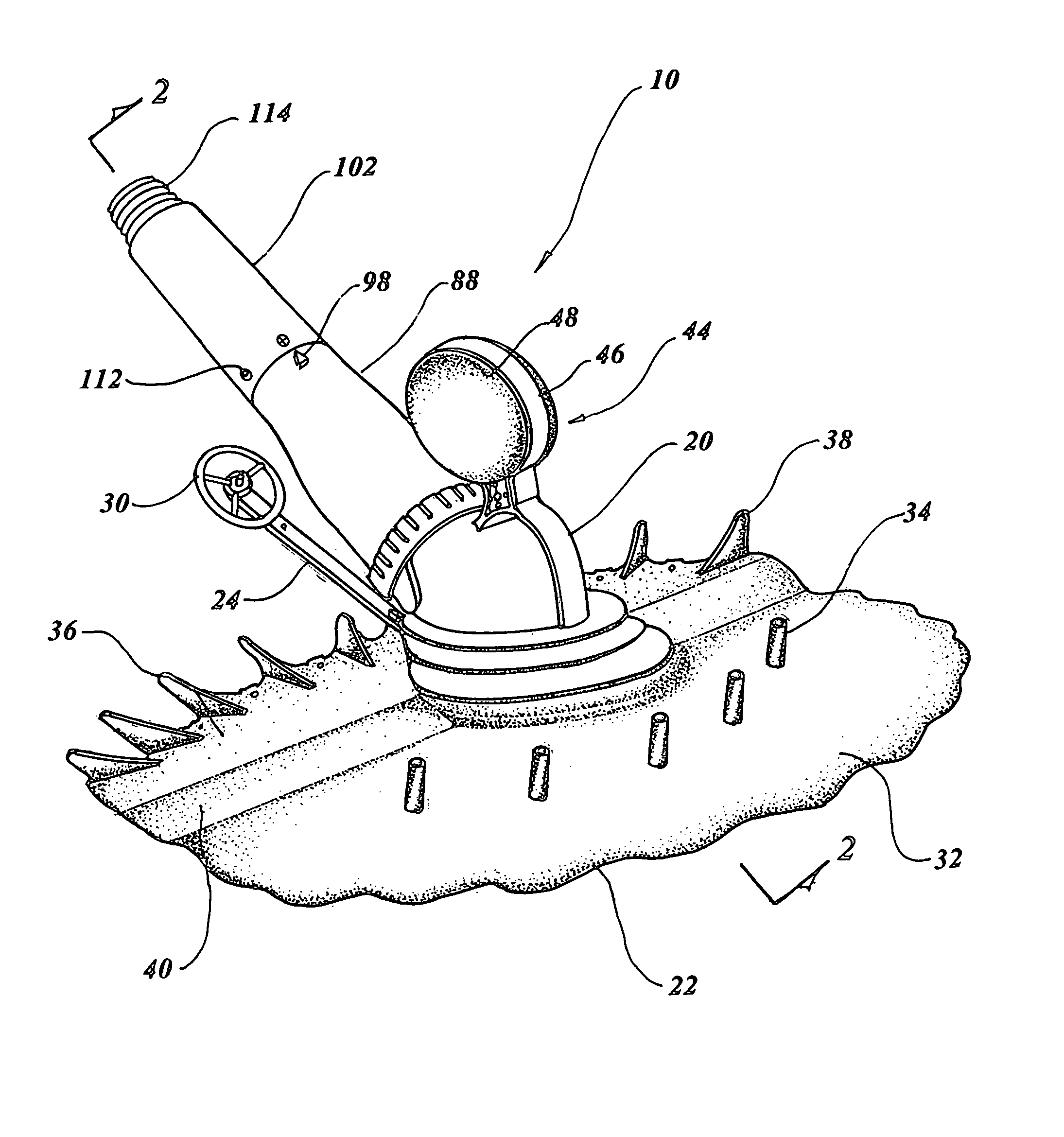
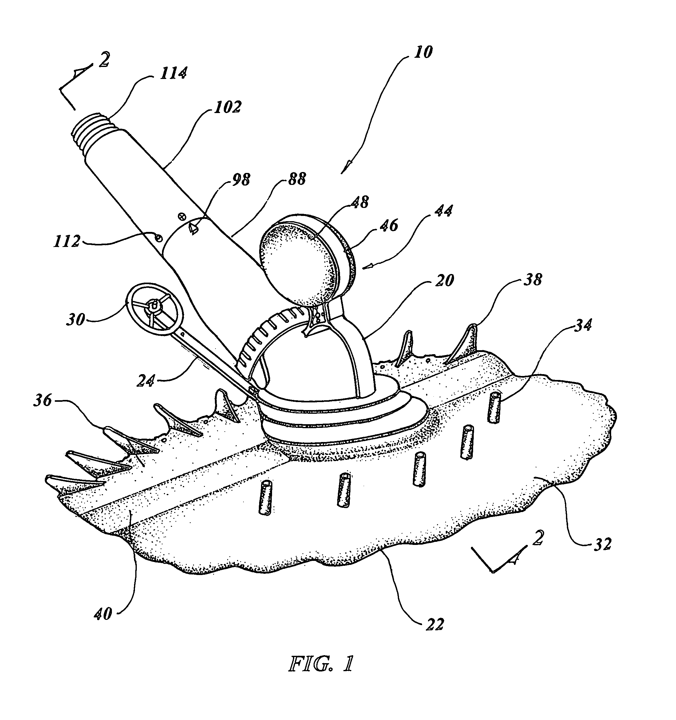
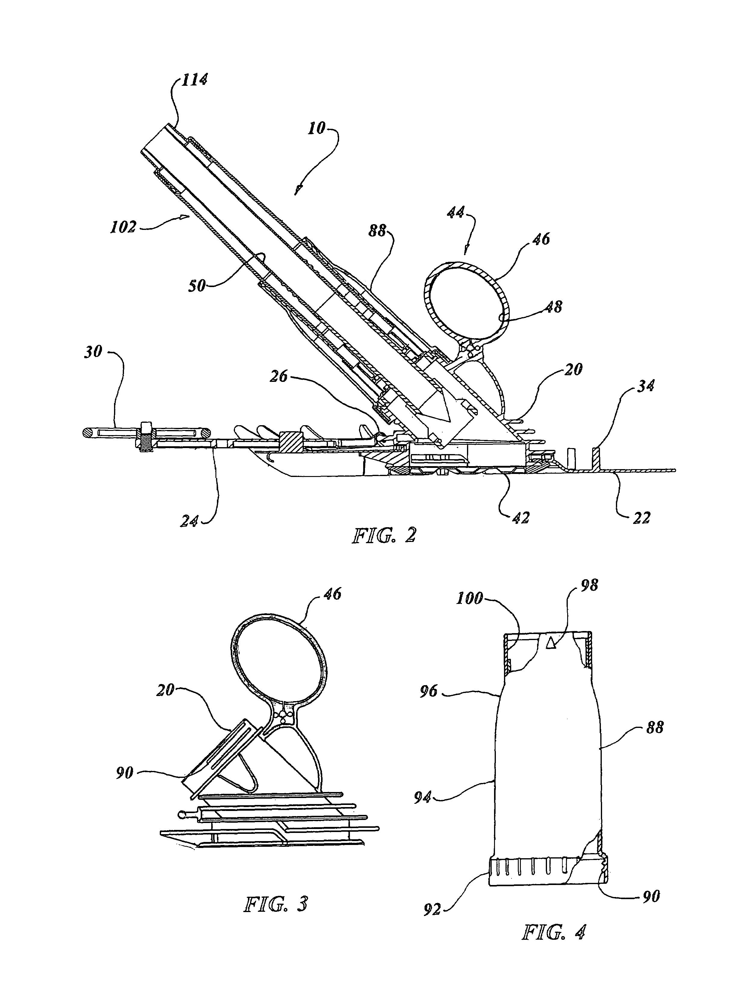
[0064]The best mode for carrying out the invention is presented in terms of a preferred embodiment for an adjustable flow pulsating pool sweep 10. This preferred embodiment is shown in FIGS. 1 thorough 35 and consists of a lower pool sweep body 20 having a resilient skirt 22 attached underneath, as illustrated in FIGS. 1-3 and 26-29. A hinged deflector arm 24 is attached to the lower pool sweep body 20 with a hinge joint 26 and the resilient skirt 22. An arm attaching upstanding finger 28 formed in an arrow head shape, as shown in the FIG. 30, and attaches the arm 24 to the skirt 22.

[0065]The distal end of the hinged deflector arm 24 incorporates a rotatable deflector wheel 30, such that when the pool sweep 10 is being propelled within a pool, direction is changed when the wheel 30 touches an obstruction permitting the pool sweep 10 to continue operation.

[0066]The resilient skirt 22 includes a flat rear portion 32, with a plurality of posts 34, and a raised front portion 36, having ...


PUM


Abstract

An adjustable pulsating submersible (10) is taught consisting of, a lower pool sweep body (20) with a resilient skirt (22) attached underneath. An integrated valve (50) is positioned within the lower pool sweep body and is used to accomplish a preliminary pre-selected flow adjustment. An upper pool sweep body (88) is placed over the integrated valve and is attached to the lower pool sweep body with threads in no more than one quarter turn. A flow adjuster (102) is slid tightly into upper pool sweep body and includes a number of first flow openings (104). A flow gate (106) is slid onto the flow adjuster and may rotate within limits with the flow adjuster. The flow gate incorporates a number of second flow openings (108) aligned with the first flow openings, when the flow adjuster is manually rotated the second flow openings misalign with the first flow openings providing precise adjustable flow operation.

Description

TECHNICAL FIELD[0001]The present invention relates to swimming pool cleaning devices in general. More specifically to a flow adjustable submersible pulsating pool sweep actuated by hydraulic pressure reacting with torsion spring loaded valve plates in combination with an adjustable hydraulic pressure opening relief valve having regulated flow control openings.BACKGROUND ART[0002]Previously, many types of pool cleaners have been used in endeavoring to provide an effective means for producing a pulsating effect with a submersible pulsating pool cleaner to propel the sweep of cleaner around the pool bottom and sides using the suction of the pool cleaner pump for removing debris and foreign matter from the swimming pool. A myriad of types of cleaners and sweeps have been employed in the past causing the interruption of induced flow due to kinetic energy of the water flow transferring force to the cleaner using the inertia of the fluid, which in turn promotes the desired linear movement ...

Claims


Application Information

Patent Timeline
Patent Type & Authority Patents(United States)
IPC IPC(8): E04H4/16
CPCE04H4/1663F16K15/035
Inventor CHANG, PAUL C.
Owner CHANG PAUL C
Why Eureka
Try Eureka