Fixing mechanism of a lathe

a technology of fixing mechanism and lathe, which is applied in the direction of turning machine accessories, automatic conveying/guiding stock, manufacturing tools, etc., can solve the problems of reducing affecting the switching action of the working platform, and increasing the length of time spent switching the working platform, so as to increase the efficiency of the lathe and ensure the operation. safety

Inactive Publication Date: 2008-10-14
FACTORY AUTOMATION TECH CO LTD
View PDF3 Cites 0 Cited by
  • Summary
  • Abstract
  • Description
  • Claims
  • Application Information

AI Technical Summary

Benefits of technology

[0009]It is a main object of the invention to provide an improvement on a fixing mechanism of a lathe, which prevents switching action of the working platforms from being interfered with, and allows a moving shaft thereof to move a shorter distance in securing / releasing the working platforms, thus increasing efficiency of the lathe and safety of operation.

Problems solved by technology

2. The fixing mechanism sticks out for a certain distance: to release a working platform, the gripping claw of the fixing mechanism will have to stick out from the joint between the fixing mechanism and the working platform. Therefore, the gripping claw has to move upwards for a longer distance for allowing the switching action of the working platforms, increasing the length of time spent in switching the working platforms, and reducing efficiency of the lathe. Furthermore, the gripping claw could interfere with the switching action of the working platforms.
1. It isn't environment friendly to use oil hydraulic devices: oil in oil hydraulic devices is prone to pollute the environment, and difficult to dispose of, and oil hydraulic devices consume electric power, and have to be maintained regularly. And, the oil containers occupy much space.

Method used


Image

  • Fixing mechanism of a lathe
  • Fixing mechanism of a lathe
  • Fixing mechanism of a lathe

Examples


Embodiment Construction

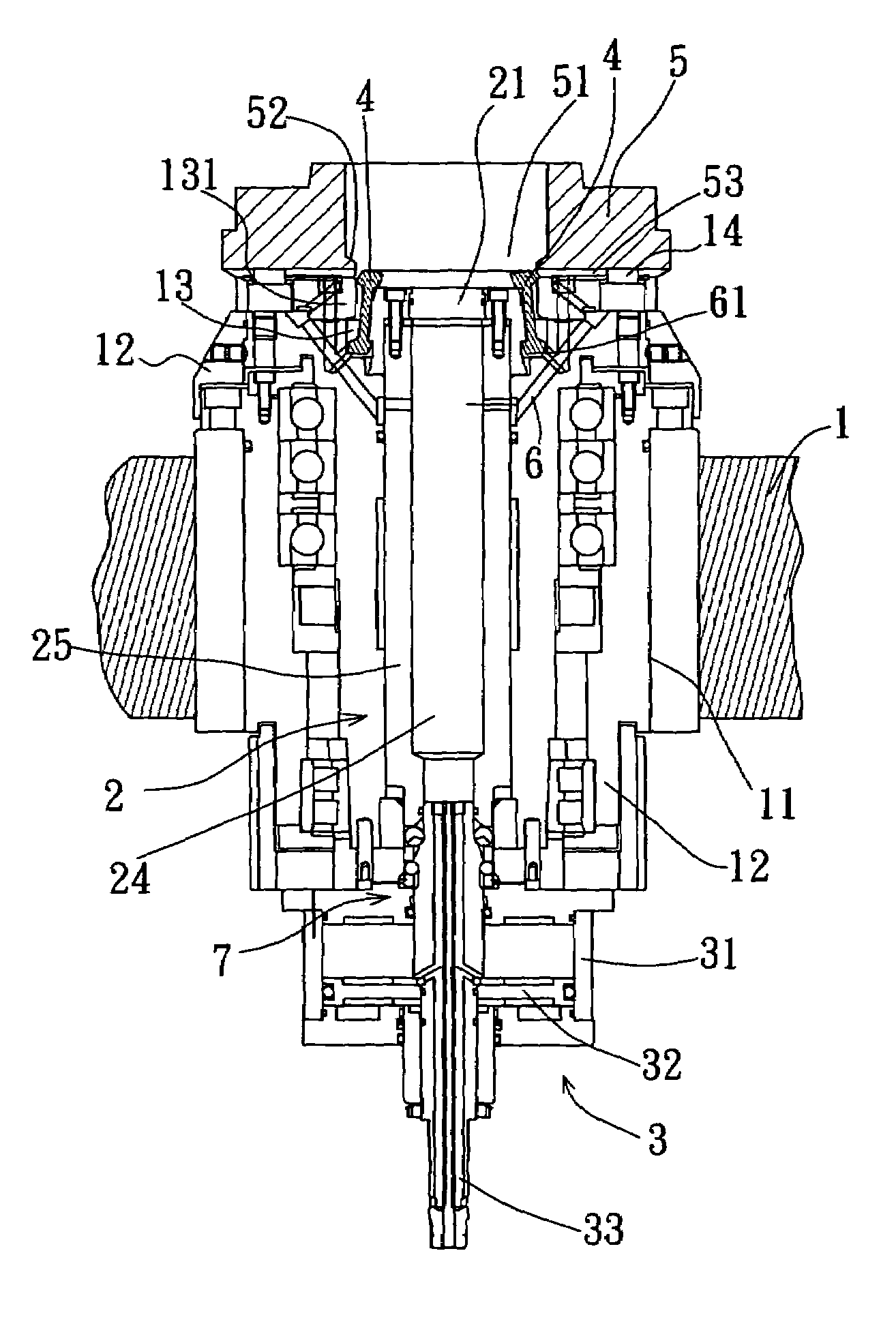
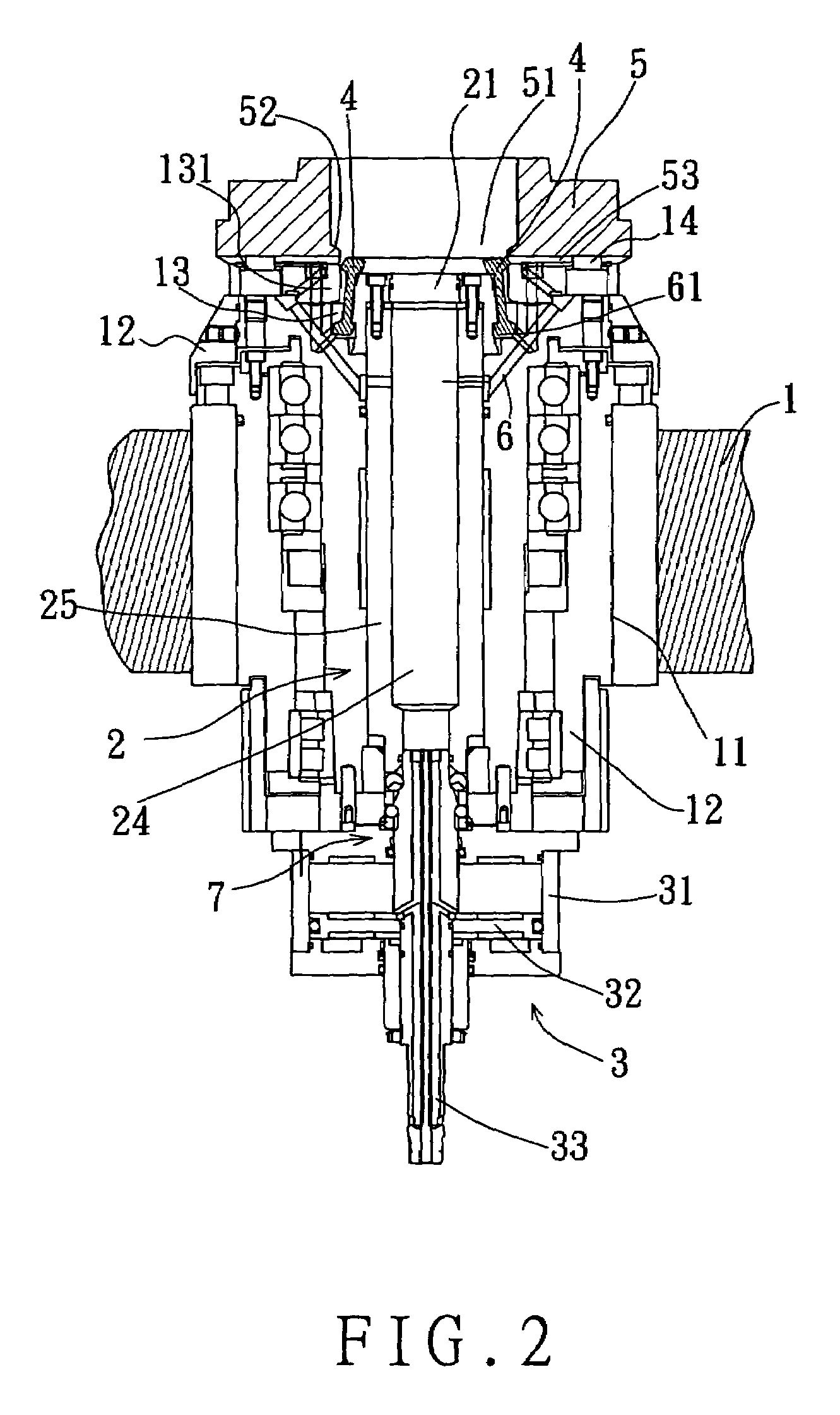
[0018]Referring to FIGS. 2 to 6, a preferred embodiment of a fixing mechanism of a lathe includes:

[0019]a stock 1, the stock 1 has a through hole 11, and a shaft seat 12 secured in the through hole 11; the shaft seat 12 has a hollow holding portion 13 at one end, a protruding portion 131 on an inner side of the hollow holding portion 13, and a step 132 in a lower section of the hollow holding portion 13;

[0020]a moving shaft 2, the moving shaft 2 is passed in the shaft seat 12 in an up and down movable manner; the moving shaft 2 has a shaft head 21 at one end, which projects into the hollow holding portion 13 of the shaft seat 12 of the stock 1; the shaft head 21 has first and second step-shaped portions 22 and 23; the first step-shaped portion 22 has a peg-like cross-section, and has a pushing side 221, and a lower pulling side 222; the second step-shaped portion 23 has a cross-section like a triangle cone, and it has a propping side 231;

[0021]a power source 3, the power source 3 is...


PUM

PropertyMeasurementUnit
pushing forceaaaaaaaaaa
forceaaaaaaaaaa
distanceaaaaaaaaaa

Abstract

A lathe includes a stock, a shaft, a power source, gripping bars, and a platform; the stock has a shaft seat secured therein, which has a hollow holding portion, and an inner protrusion; the shaft is passed in the shaft seat in a movable manner, and has a head having a step-shaped portion and projecting into the holding space; the power source is used for actuating the shaft; the gripping bars are spaced around the shaft head, and each have inner and outer recesses; the platform has a hollow portion, and an inner protrusion right above and facing the inner protrusion of the shaft seat; when the shaft is moved upwards, the step-shaped portion will be pressed against upper edges of the inner recesses to raise the gripping bars; thus, both the protrusions are tightly held within the outer recesses of the gripping bars, and the working platform secured in position.

Description

BACKGROUND OF THE INVENTION[0001]1. Field of the Invention[0002]The present invention relates to a fixing mechanism of a lathe, more particularly one, which includes several gripping bars hiding therein instead of sticking out such that switching action of the working platforms can't be interfered with, and the fixing mechanism will move a shorter distance in securing / releasing the working platforms, thus increasing efficiency of the lathe and the safety of operation.[0003]2. Brief Description of the Prior Art[0004]Lathes are important machining apparatuses, and they are grouped into horizontal lathes and vertical ones, which are different in the position of the cutting tools. Referring to FIG. 1, a currently existing vertical lathe 9 includes a supporting frame 91, cutting tools 92, two door planks 93, a rotating disk 94, and two working platforms 95. The cutting tools 92 are positioned in a holding space of the supporting frame 91. The door planks 93 are pivoted to the supporting ...

Claims


Application Information

Patent Timeline
Patent Type & Authority Patents(United States)
IPC IPC(8): B23B7/06B23B1/00
CPCB23B31/4033Y10T82/2566Y10T82/25Y10T82/2514
Inventor LU, YUNG-HSIANGLIN, CHUNG-LUNG
Owner FACTORY AUTOMATION TECH CO LTD
Why Eureka
Try Eureka