Driving force control apparatus for four-wheel drive vehicle

a technology of driving force control and four-wheel drive, which is applied in the direction of process and machine control, braking systems, instruments, etc., can solve the problems of vehicle not being stably launched on a level road, vehicle failure to stably launch, and vehicle failure to achieve stable launch, so as to prevent control from hunting

Active Publication Date: 2008-10-14
ZIMMERMANN MARY ASHLEY +1
View PDF10 Cites 14 Cited by
  • Summary
  • Abstract
  • Description
  • Claims
  • Application Information

AI Technical Summary

Benefits of technology

[0012]As described above, when the vehicle is in the slip stop state, the fastening force of the clutch is corrected to correct the distribution of the torque between the front and rear main / sub-driving wheels, thus making it possible to increase a driving force transmitted, for example, to the wheels other than a slipping wheel. In this way, the vehicle can be launched without fail even on any of a road with a uniform surface resistance and a split road.
[0015]In this way, a timing at which the clutch is corrected for the fastening force is delayed by the first predetermined time from the time at which the rotational speed of any of the wheels falls to the predetermined rotational speed or lower. In other words, the determined slip stop state is definitely determined after the predetermined time, so that the distribution of the torque between the main and sub-driving wheels is corrected when the vehicle is definitely in the slip stop state, thus making it possible to stably launch the vehicle while preventing the hunting of the control.
[0017]According to this preferred embodiment of the driving force control apparatus for a four-wheel drive vehicle, the counting means counts the number of times the vehicle is determined to be in the slip stop state, such that the fastening force correcting means corrects the clutch for the fastening force in accordance with the counted number. Therefore, for example, the clutch can be corrected for the fastening force such that it increases in accordance with an increase in the counted number. In this way, by gradually increasing the torque distributed between the main driving wheels and the sub-driving wheels in accordance with the counted number, the vehicle can be smoothly launched, while preventing a sudden change in the distribution of the torque even when a larger driving force is required for launching, for example, on a gradient road.
[0020]In this way, the control can be prevented from hunting by definitely determining that the vehicle has exited the slip stop state only after it is ensured that the vehicle has exited the slip stop state. Also, since the fastening force correcting means continues to correct the clutch for the fastening force for the second predetermined time until it is definitely determined that the vehicle has exited the slip stop state, the vehicle can be smoothly run immediately after it gets out of the slip stop state, i.e., immediately after it is launched.

Problems solved by technology

However, the driving force control apparatus disclosed in Japanese Patent Publication No. 8-19981 described above can experience difficulties in stably launching a vehicle for the reasons set forth below on a road which is not uniform in surface condition and has variations in surface resistance for each wheel (hereinafter called the “split road”).
However, if the front wheels are slipping when the vehicle is launched on a gradient road, the control characteristic suitable for a level load can distribute an insufficient torque to the rear wheels to possibly fail a stable launch.
Conversely, when the control characteristic is set to be suitable for a gradient road, though the vehicle can be smoothly launched on a gradient road, the vehicle cannot be stably launched on a level road due to an excessive torque distributed to the rear wheels, when the front wheels are slipping, to cause the vehicle to slide sideways.
Also, in the event of a launch associated with slipping as mentioned above, even if the selected control characteristic is changed to another control characteristic to distribute a different torque to the rear wheels in response, the vehicle cannot still be stably launched due to a difference in torque which occurs upon switching the control characteristic.

Method used


Image

  • Driving force control apparatus for four-wheel drive vehicle
  • Driving force control apparatus for four-wheel drive vehicle
  • Driving force control apparatus for four-wheel drive vehicle

Examples


Embodiment Construction

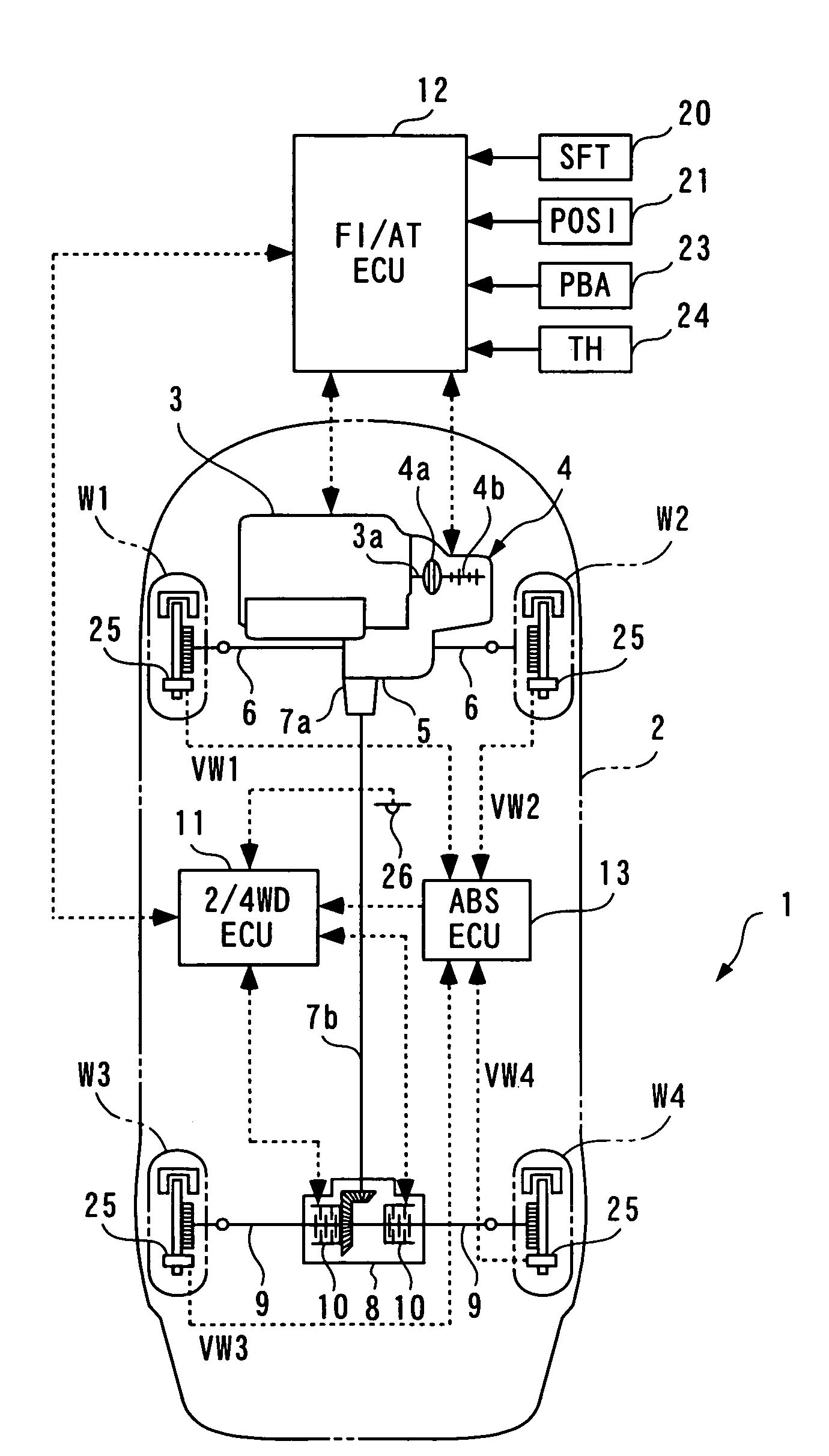
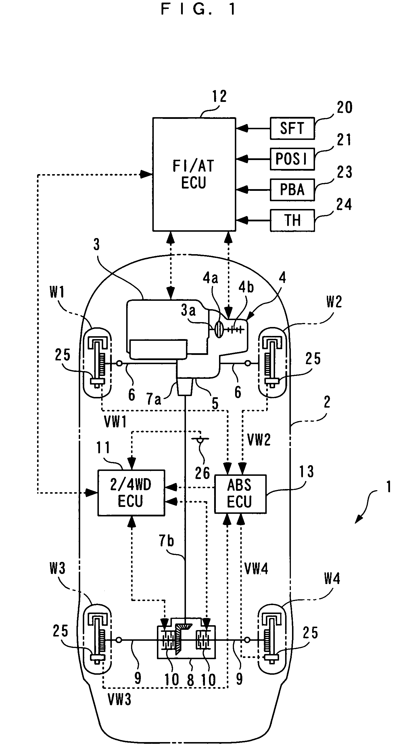
[0037]In the following, an embodiment of the present invention will be described in detail with reference to the accompanying drawings. FIG. 1 generally illustrates the configuration of a driving force control apparatus 1 according to one embodiment, and a four-wheel drive vehicle 2 to which the driving force control apparatus 1 is applied. As illustrated, the four-wheel drive vehicle (hereinafter simply called the “vehicle”) 2 comprises an engine 3 mounted sideways in a front region thereof (prime mover), and an automatic transmission 4 arranged integrally with the engine 3.

[0038]The automatic transmission 4 comprises a torque converter 4a coupled to an output shaft 3a of the engine 3; a shift lever (not shown) for selecting one shift position from eight shift positions consisting of 1, 2, 3, D4, D5, N, P, R; and a gear mechanism 4b (only part of which is shown) which can be switched among gear positions corresponding to six transmission ratios consisting of a first to a fifth spee...


PUM


Abstract

A driving force control apparatus for a four-wheel drive vehicle is provided for stably launching the vehicle irrespective of whichever condition of a road surface and whether or not a road is gradient. In the driving force control apparatus for a four-wheel drive vehicle configured to transmit a driving force of a prime mover directly to a left and a right main driving wheel and to a left and a right sub-driving wheel through a clutch, rotational speed sensors detect the rotational speed of the respective main driving wheels and sub-driving wheels, a 2 / 4 WD•ECU sets a fastening force of the clutch in accordance with a difference between the detected rotational speeds of the main driving wheels and the sub-driving wheels, determines that the four-wheel drive vehicle is in a slip stop state when at least one of the detected rotational speeds of the wheels is equal to or lower than a predetermined rotational speed, and corrects the clutch for the set fastening force when it determines that the four-wheel drive vehicle is in the slip stop state.

Description

BACKGROUND OF THE INVENTION[0001]1. Field of the Invention[0002]The present invention relates to a driving force control apparatus for a four-wheel drive vehicle which controls the distribution of a driving force to main driving wheels and sub-driving wheels.[0003]2. Description of the Prior Art[0004]A conventional driving force control apparatus for a four-wheel drive vehicle of the type mentioned above is known, for example, from one disclosed in Japanese Patent Publication No. 8-19981. In this four-wheel drive vehicle (hereinafter simply called the “vehicle”), a torque of a power plant having an engine, a transmission and the like is transmitted to front wheels and rear wheels from an output shaft of the power plant through a front wheel and a rear wheel propeller shaft, respectively. Also, a hydraulic clutch is disposed between the output shaft and the rear wheel propeller shaft, such that the driving force control apparatus controls a fastening force of this clutch to control t...

Claims


Application Information

Patent Timeline
Patent Type & Authority Patents(United States)
IPC IPC(8): B60K17/35
CPCB60K17/35B60K23/0808
Inventor SUGO, YASUHIKOHARA, JIRO
Owner ZIMMERMANN MARY ASHLEY
Why Eureka
Try Eureka