

Perforated soundproof structure and method of manufacturing the same
a technology of perforated and perforated walls, which is applied in the direction of walls, instruments, transportation and packaging, etc., can solve the problems of repeated experimental manufacture, insufficient insulation of wide frequency bandwidth noise, and insufficient sound absorbing performance to noises other than the resonance frequency f, etc., to achieve excellent sound absorbing performance, wide frequency bandwidth, and sufficient sound absorbing performan
Inactive Publication Date: 2008-10-14
KOBE STEEL LTD
View PDF35 Cites 15 Cited by
- Summary
- Abstract
- Description
- Claims
- Application Information
AI Technical Summary
Benefits of technology
[0009]Since this perforated soundproof structure is formed by use of the internal plate having the thickness, hole diameter and open area ratio satisfying the design conditions to give rise to the viscous effect in the air, the conversion of air vibration to thermal energy by the viscous effect is promoted. Consequently, sufficient sound absorbing performance can be surely exhibited at a wide frequency bandwidth. This structure thus has excellent sound absorbing performance to, in addition to the noise of the resonance frequency, noises other than this frequency.
[0050]According to this structure, since the thickness, hole diameter and open area ratio of the internal plate satisfying the design conditions to give rise to the viscous effect in the air are preliminarily determined with the sound source to be insulated being 70 dB or more, and at least the hole diameter of the through-holes is then set to 3 mm or less, a perforated soundproof structure excellent in sound absorbing performance can be completed at a lower cost in a shorter time than in the determination of the design conditions of suitable thickness, hole diameter and the like by trial and error. Since the sound source to be isolated is 70 dB or more, a perforated soundproof structure according to noise source can be provided.
Problems solved by technology
Accordingly, the conventional structures, as described above, have the problem that noises of a wide frequency bandwidth cannot be sufficiently insulated because the sound absorbing performance to noises other than the resonance frequency f is often extremely inferior.
They also have the problem that experimental manufacture must be repeated until parameters for excellent sound insulating performance can be obtained in the determination of parameters based on the above-mentioned general equation.
On the other hand, a drive mechanism such as engine is not only a generating source of noise but also a generating source of mechanical vibration.
At this time, even if designed according to the above general equation of the Helmholz resonance principle, the noise-proof cover is excited by the vibration of the drive mechanism, and the noise-proof cover itself, as a result, vibrates to generate noise.
Accordingly, its soundproof performance is insufficient as a noise-proof cover for automobile that is mechanically excited, too.
Method used
View moreImage
Smart ImageViewing Examples

Examples
example
[0123]As described above, the perforated soundproof structures constituted as shown in FIGS. 11-16 were examined for absorption coefficient and radiated sound pressure level. In the examination, the structures of FIGS. 11, 12, 13, 14, 15 and .16 were taken as Examples 1, 2, 3, 4, 5 and 6, respectively. As the examination results of Examples 1-6 are shown in FIG. 18 for the absorption coefficient and in FIG. 19 for the radiated sound pressure level, respectively.
Login to View More PUM
 Abstract
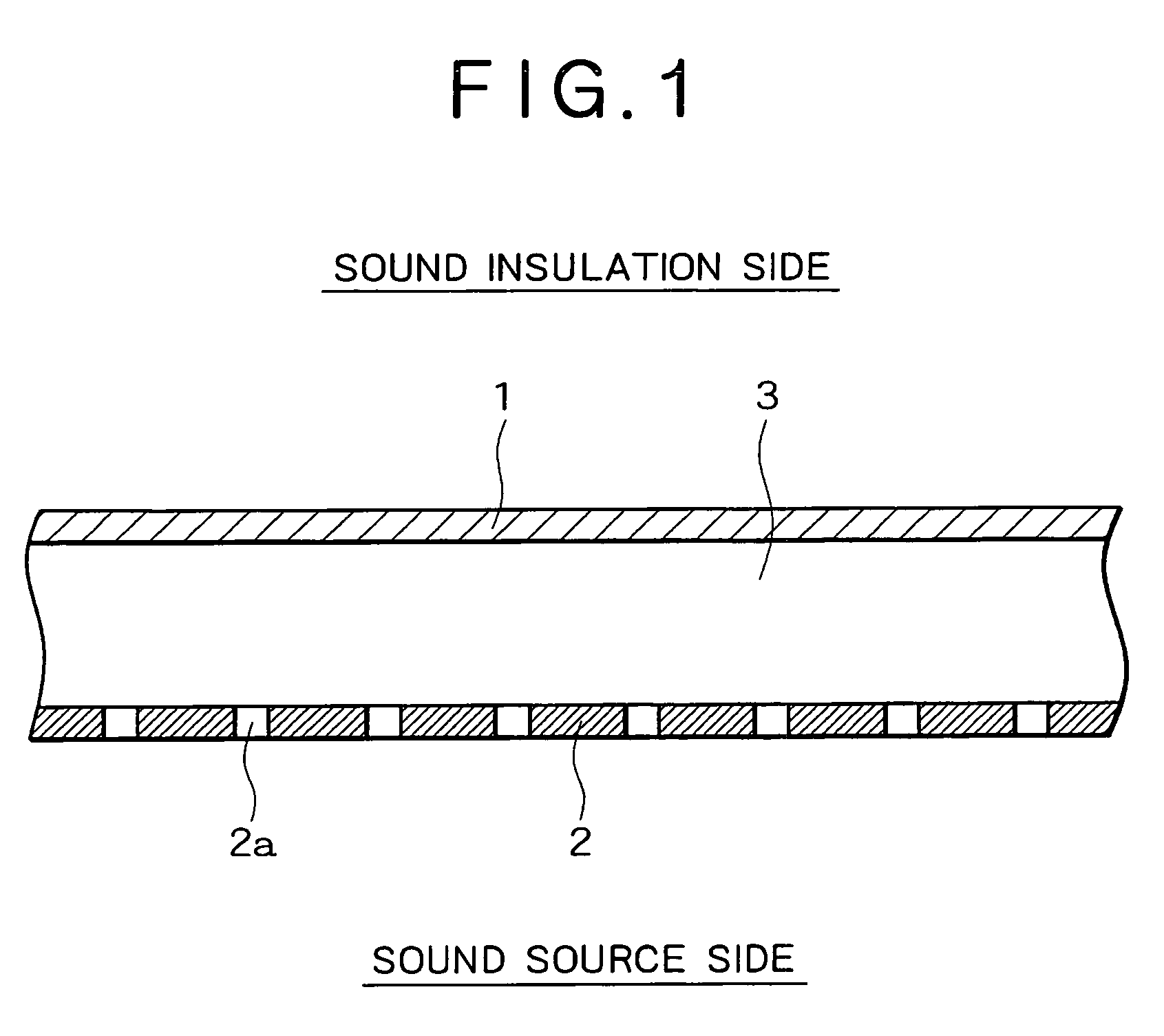
A perforated soundproof structure is formed by oppositely arranging an external plate 1 and an internal plate 2 having a number of through-holes 2a. The board thickness, hole diameter and open area ratio of the internal plate 2 are set to satisfy design conditions to give rise to a viscous effect in the air passing through the through-holes 2a, and the design conditions are set so that the frequency bandwidth to attain an absorption coefficient of 0.3 or more is 10% or more of the resonance frequency.
Description
TECHNICAL FIELD[0001]The present invention relates to a perforated soundproof structure for reducing sounds from a noise generating source, and a method of manufacturing the same.BACKGROUND ART[0002]In recent years, a perforated soundproof structure for insulating sounds by the Helmholz resonance principle by oppositely arranging an internal plate having a number of through-holes formed on the whole surface and an external plate through an air layer have attracted attention. For example, in Japanese Patent Application Laid-open (Kokai) No. 6-298014, there is disclosed, focusing on that the general equation of the Helmholz resonance principle is “f=(c / 2π)×√{square root over ( )}{β / (t+1.6b)d}”, a perforated sound insulating structure constituted to efficiently reduce noise of a specified resonance frequency f based on this general equation. In the above general equation, the resonance frequency f is represented by use of sound velocity c, open area ratio β, board thickness of internal...
Claims
Login to View More Application Information
Patent Timeline
 Patent Type & AuthorityPatents(United States)
IPC IPC(8): E04B1/82E04B1/84E04B2/02E04B1/74G10K11/16G10K11/168G10K11/172
CPCG10K11/172Y10T428/24322
InventorYAMAGIWA, ICHIROTANAKA, TOSHIMITSUUEDA, HIROKIUTSUNO, HIDEOSAKATANI, TORUSUGIMOTO, AKIO
OwnerKOBE STEEL LTD