Porous Sound Absorbing Structure

a sound absorbing structure and porous technology, applied in the direction of walls, flooring, instruments, etc., can solve the problems of clogging through holes, affecting exerting the sound absorbing effect, so as to achieve sufficient sound absorbing performance and promote the conversion of air vibration

Inactive Publication Date: 2007-11-29
KOBE STEEL LTD
View PDF15 Cites 45 Cited by
  • Summary
  • Abstract
  • Description
  • Claims
  • Application Information

AI Technical Summary

Benefits of technology

[0006] A porous sound absorbing structure according to one aspect of the present invention is a porous sound absorbing structure in which a first outside member and at least one inside member are arranged while opposed to each other, many through holes being made along a flat plane in the inside member, and a plate thickness of the inside member and a diameter and an aperture ratio of the through hole are set so as to generate an viscous effect in air passing through the through hole. In the porous sound absorbing structure, a second outside member is arranged while opposed to the inside member, the second outside member being located on the side opposite to the first outside member with respect to the inside member, many through holes being made along the flat plane in the second outside member, and the aperture ratio of the through hole in the second outside member is more than 3% and not more than 50% (claim 1).
[0007] According to the porous sound absorbing structure according to the present invention, the aperture ratio of the second outside member exceeds 3%, which promotes the conversion of the air vibration into the heat energy by the viscous effect of the through hole in the inside member, and the sufficient sound absorbing performance can be exerted in the wide frequency band. Additionally, because the aperture ratio of the second outside member becomes not more than 50%, the rigidity of the second outside member can be secured to some extent.

Problems solved by technology

However, when the Helmholtz resonance principle is used, there is a problem that a soundproof effect is exerted only to the sound having the particular resonance frequency while the soundproof effect is extremely lowered to the sounds having frequencies except for the resonance frequency.
However, in the porous soundproof structure, the interior plate is exposed on a sound source side, and the diameter of the through hole is extremely small, so that sometimes clogging is generated in the through hole.
Furthermore, sometimes the diameter of the through hole cannot be decreased due to constraints from other functions (drainage, painting, and the like).
Thus, because the size of the through hole diameter is subject to the restraint, there is a problem that the frequency band in which the sound absorbing performance can be exerted becomes narrowed.

Method used


Image

  • Porous Sound Absorbing Structure
  • Porous Sound Absorbing Structure
  • Porous Sound Absorbing Structure

Examples


first embodiment

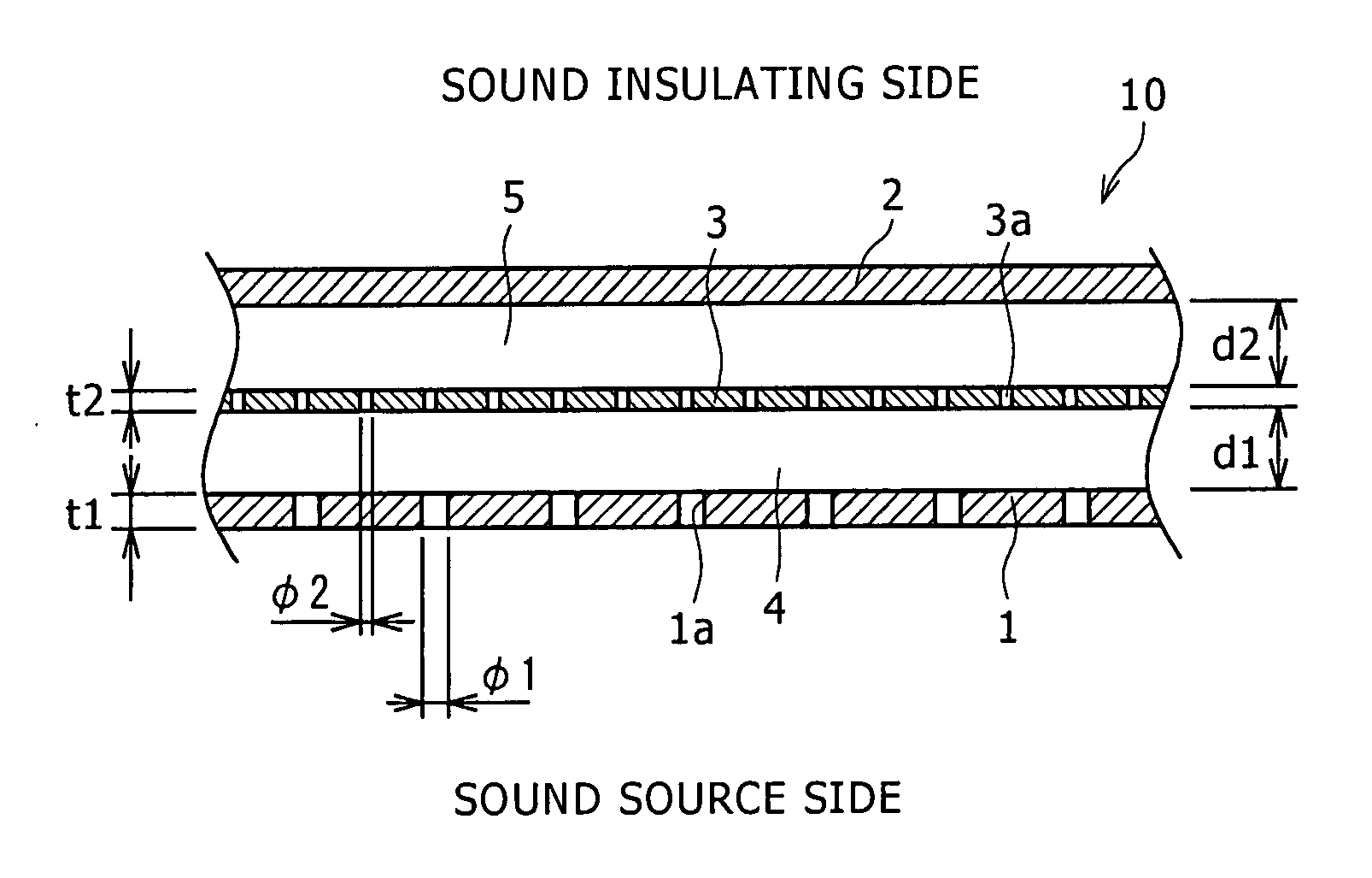
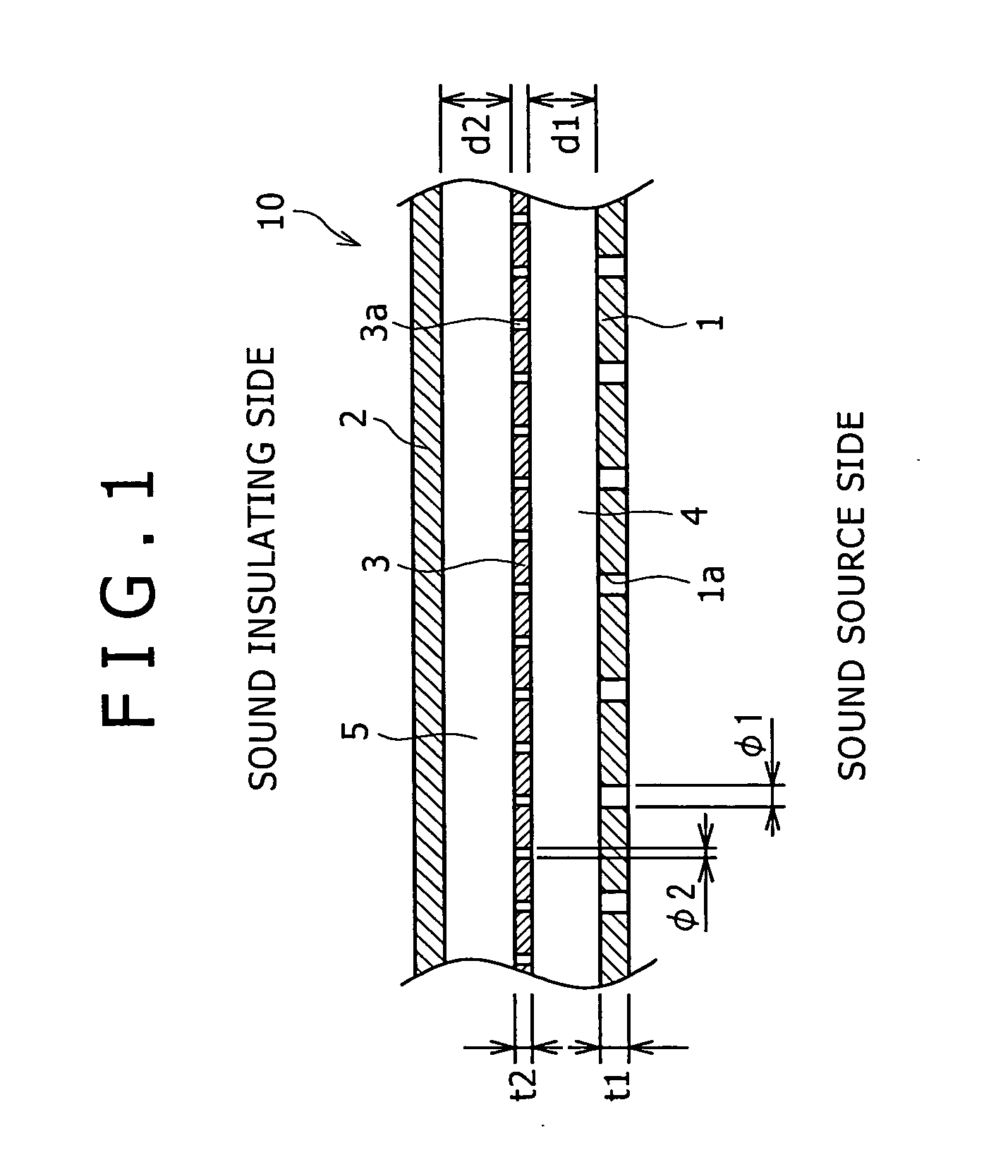
[0045]FIG. 1 is a transverse sectional view showing a porous sound absorbing structure according to a first embodiment of the present invention. As shown in FIG. 1, a porous sound absorbing structure 10 according to the first embodiment includes an exterior plate (second outside member) 1, a closing plate (first outside member) 2, and an interior plate (inside member) 3. The exterior plate 1 is arranged on the sound source side, the closing plate 2 is arranged on the sound insulating side, and the interior plate 3 is arranged between the exterior plate 1 and the closing plate 2. An air layer 4 is located between the interior plate 3 and the exterior plate 1, and an air layer 5 is located between the interior plate 3 and closing plate 2. The exterior plate 1, the closing plate 2, and the interior plate 3 are made of a metal such as iron and aluminum, a synthetic resin, a fiber reinforced material, and the like. Desirably the exterior plate 1, the closing plate 2, and the interior pla...

second embodiment

[0058]FIG. 7 is a transverse sectional view showing a porous sound absorbing structure according to a second embodiment of the present invention. As shown in FIG. 7, a porous sound absorbing structure 20 of the second embodiment has the substantially same configuration as the porous sound absorbing structure 10 of the first embodiment except that a glass wool (sound absorbing material) 21 is arranged in the air layer 5 of the porous sound absorbing structure 10 of the first embodiment. In FIG. 7, the same component as the first embodiment is designated by the same numeral, and the description will be omitted.

[0059] In the second embodiment, although the glass wool 21 is provided in the air layer 5, for example, the sound absorbing material made of the metal fiber, the foam metal and resin metal thin film or the metal thin film, or the non-oven cloth may be provided in the air layer 5. The glass wool 21 may be provided not only in the air layer 5 but in the air layer 4, or the glass...

third embodiment

[0061]FIG. 8 is a transverse sectional view showing a porous sound absorbing structure according to a third embodiment of the present invention. As shown in FIG. 8, a porous sound absorbing structure 30 of the third embodiment has the substantially same configuration as the porous sound absorbing structure 10 of the first embodiment except that multiple thin films 31 are arranged so as to vertically partition the air layer 5 of the porous sound absorbing structure 10 of the first embodiment. In FIG. 8, the same component as the above-described embodiments is designated by the same numeral, and the description will be omitted.

[0062] In the multiple thin films 31, two thin films 32 and 33 are laminated while being adjacent to each other. Many through holes 32a and 33a are made in the thin films 32 and 33 respectively, and the through holes 32a and 33a have the same aperture ratios and diameters as the interior plate 3. As shown in FIG. 8, the through holes 32a and 33a in the two thin...


PUM


Abstract

A porous sound absorbing structure 10 includes an exterior plate 1 and a closing plate 2 in order to suppress a decrease in sound absorbing performance in a wide frequency band. An interior plate 3 is arranged between the exterior plate 1 and the closing plate 2, and air layers 4 and 5 are located between the exterior plate 1 and the interior plate 3 and between the interior plate 3 and the closing plate 2 respectively. The exterior plate 1, the interior plate 3, and the closing plate 2 are arranged while opposed to each other. Many through holes 1a and 3a are made in the exterior plate 1 and the closing plate 2 respectively. In the interior plate 3, a plate thickness t2 and a diameter φ2 and an aperture ratio β2 are set so as to generate an viscous effect in air passing through the through hole 3a. The aperture ratio β1 of the through hole 1a in the exterior plate 1 is set more than 3% and not more than 50%.

Description

TECHNICAL FIELD [0001] The present invention relates to a porous sound absorbing structure which reduces sound from a noise emitting source. BACKGROUND ART [0002] Recently, a porous soundproof structure is becoming operational in various fields. In the porous soundproof structure, a plate member in which a hole is not made and a plate member in which many through holes are made over a surface are arranged on an outside and an inside with respect to a sound source while opposed to each other through an air layer, and thereby a Helmholtz resonance principle is utilized to perform noise control. When the Helmholtz resonance principle is utilized, for example, a relationship of a general formula f=(c / 2π)×∫{β / (t+1.6φ)d} holds, where f is a resonance frequency, c is sound velocity, β is an aperture ratio, t is a plate thickness of the inside plate, φ is a diameter of the through hole, and d is an air layer thickness. Air in the portion of the through hole is drastically vibrated to the so...

Claims


Application Information

Patent Timeline
Patent Type & Authority Applications(United States)
IPC IPC(8): E04B1/82G10K11/16G10K11/172
CPCG10K11/16G10K11/172B32B3/10G10K11/00
Inventor YAMAGUCHI, ZENZOTANAKA, TOSHIMITSUYAMAGIWA, ICHIROUEDA, HIROKIHINO, MITSUO
Owner KOBE STEEL LTD
Why Eureka
Try Eureka