Brake cable connecting apparatus

a technology of connecting apparatus and brake cable, which is applied in the direction of mechanical equipment, braking systems, transportation and packaging, etc., to achieve the effect of reducing not only material cost but processing cost, and avoiding the burden of adjusting the insertion depth of the connecting pin

Inactive Publication Date: 2008-10-14
NISSHINBO IND INC
View PDF6 Cites 8 Cited by
  • Summary
  • Abstract
  • Description
  • Claims
  • Application Information

AI Technical Summary

Benefits of technology

[0008]The brake cable connecting apparatus according to the invention mainly comprises a regulating projection in the strut, which regulates the insertion depth of the connecting pin, to reduce the manual, complicated burden of inserting the connecting pin into the clevis of the brake cable.
[0010]In the brake cable connecting apparatus according to the invention, the regulating projection, that regulates the insertion depth of the connecting pin, is provided to eliminate the operation of adjusting the insertion depth of the connecting pin to the clevis of the brake cable. Therefore, the connecting pin can be precisely engaged by easy operation of inserting the connecting pin until the end thereof abuts against the regulating projection, thereby eliminating the burden of adjusting the insertion depth of the connecting pin. Moreover, if the regulating projection is formed in the side to which the connecting pin moves by its own weight to prevent the connecting pin from falling off, it is unnecessary to retain the connecting pin by fingertips. Furthermore, if the stopper which regulates the insertion position of the two facing plates of the clevis is added to the regulating projection of the strut, just by inserting the brake cable until the end of the clevis abuts against the strut, the engagement holes of the clevis move to a position where the connecting pin can be easily inserted; therefore, it is unnecessary to adjust the insertion position of the two facing plates of the clevis. In addition, because the cable disengagement restriction portion and resilient member can be formed by existing parts, this invention reduces not only the material cost but the processing cost, thereby reducing the production cost and the assembly cost.

Problems solved by technology

Moreover, if the regulating projection is formed in the side to which the connecting pin moves by its own weight to prevent the connecting pin from falling off, it is unnecessary to retain the connecting pin by fingertips.

Method used


Image

  • Brake cable connecting apparatus
  • Brake cable connecting apparatus
  • Brake cable connecting apparatus

Examples


first embodiment

Structure / Configuration

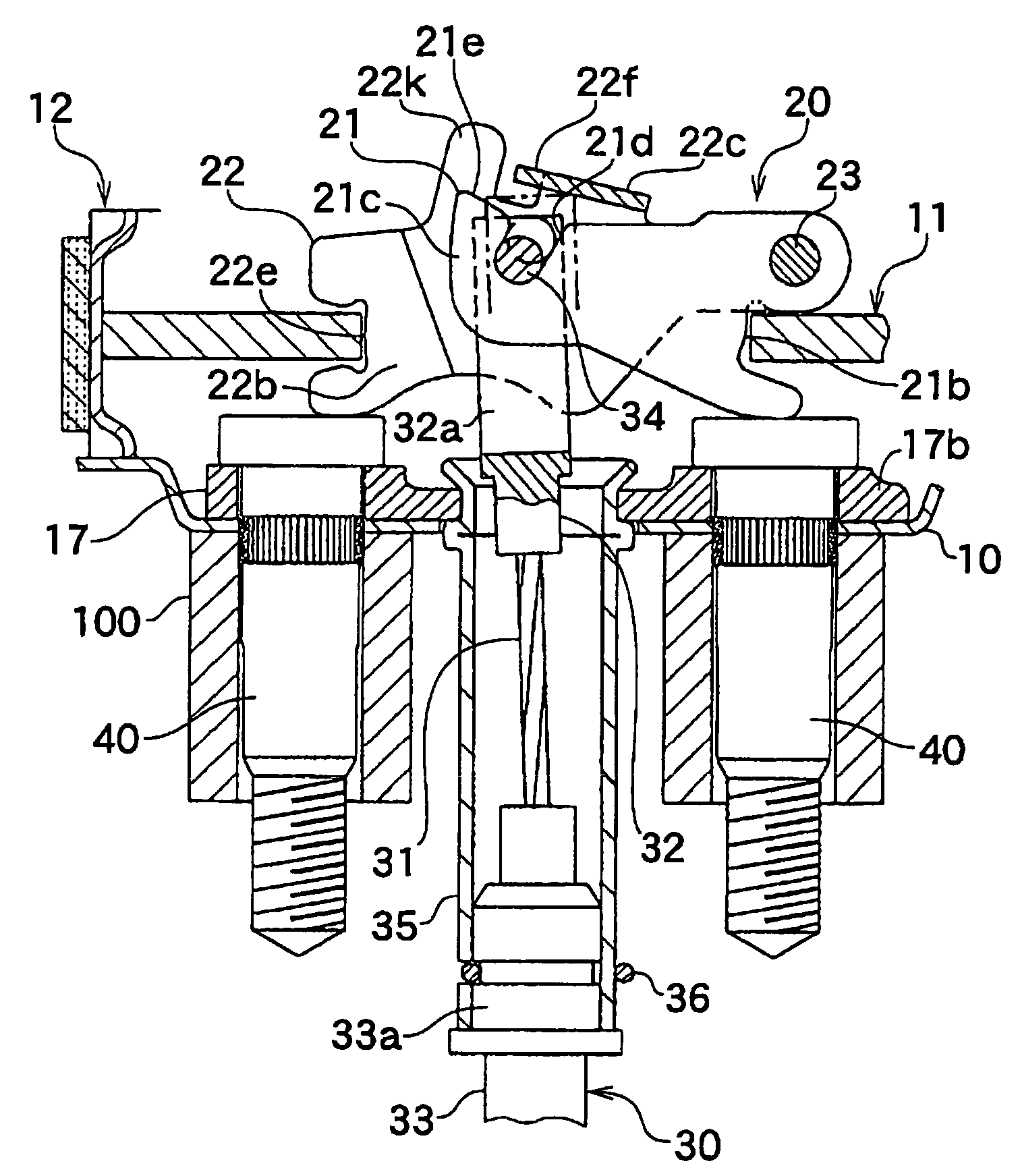
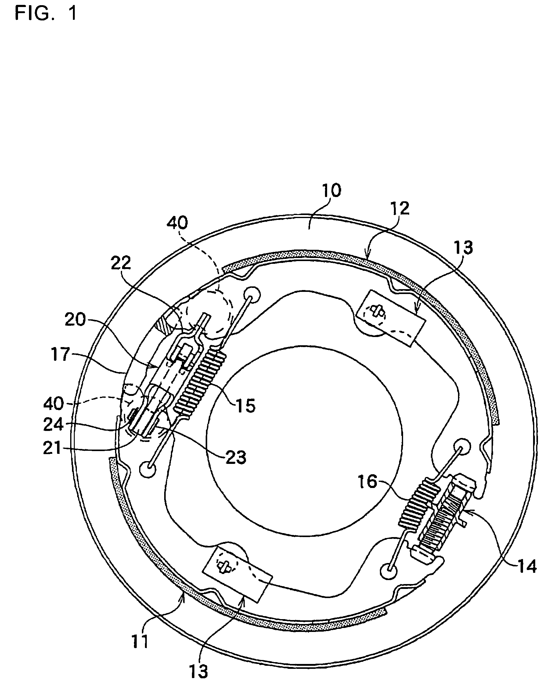
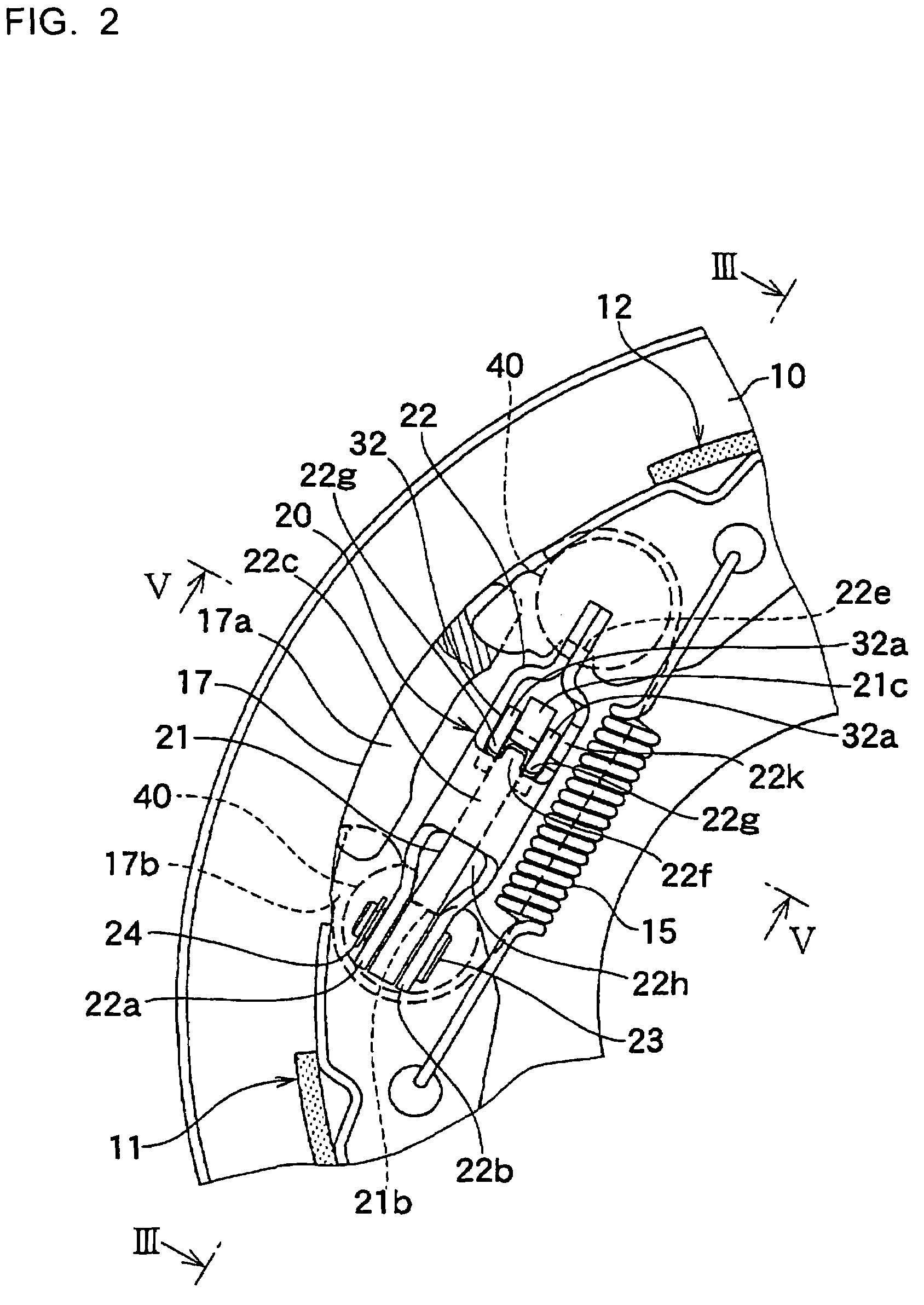
[0037]The brake cable connecting apparatus of the first embodiment of the invention will be explained with reference to FIGS. 1-9. FIG. 1 shows a plan view of a mechanical drum brake device with a brake cable connecting apparatus. The drum brake device is such that a pair of brake shoes 11, 12 are moveably supported by shoe hold mechanisms 13, 13 on a back plate 10 fixed to a stationary part (not shown in FIG. 1) of a vehicle body while one adjacent ends are supported by an anchor 17, and the other adjacent ends are connected to a connecting member 14. Both ends of the brake shoes 11, 12 abut against and are retained by an anchor 17 and a connecting member 14 by a pair of shoe return springs 15, 16 extended between both brake shoes 11, 12. A brake actuating mechanism 20, extending between both brake shoes 11, 12, that comprises a plate-like brake lever 21, a strut 22, a pivot pin 23, and a washer 24 as shown in FIGS. 2-5 and is positioned between both brake s...

second embodiment

Structure

[0061]The brake cable connecting apparatus of the second embodiment of the invention will be explained with reference to FIGS. 10-16. The embodiment shows a stopper 22m which functions to prevent over-insertion of the clevis 32 that is added to the regulating projection 22k of the strut 22 in order to arrange the engagement holes 32b, 32b of the clevis 32 to a position where the connecting pin 34 is easily inserted.

[0062]As shown in FIG. 11 and FIG. 13, the embodiment shows an example of the regulating projection 22k, to prevent over-insertion of the connecting pin 34, formed on one of the two facing surface walls 22a outside of the brake.

[0063]In consideration of the shape when the strut 22 is formed by press work, as shown in FIG. 11-13, the strut 22 of the embodiment has the bridge 22c in a different part from that of the above-described first embodiment.

[0064]The stopper 22m is formed by bending the end portion of the regulating projection 22k, which is formed on one f...

third embodiment

[0078]The brake cable connecting apparatus of the third embodiment of the invention will be explained with reference to FIGS. 17-19. In the above-explained first and second embodiments, the resilient member, which brings return force to the brake lever 21, is the existing shoe return spring. However, the resilient member can be an independent lever return spring 50 as shown in this third embodiment.

[0079]As shown in FIG. 19, the lever return spring 50 is a torsion coil spring comprising a pair of arms 51, 52 that are formed into a V shape and where the pair of arms 51, 52 converge they are bent into a loop shape to form a coil portion 53, and the free ends of each arm 51, 52 are bent at a right angle, forming hooking portions 54, 55, each having a different length.

[0080]To explain the process of placing the lever return spring 50, as shown in FIGS. 17-18, the coil portion 53 is placed on one side of the strut 22; the pair of arms 51, 52 extending from the coil portion 53 are placed ...


PUM


Abstract

A brake cable connecting apparatus that prevents a connecting pin from falling out, and whereby it is unnecessary to adjust the insertion depth of the connecting pin. The brake cable connecting apparatus comprises a regulating projection in the strut to prevent over-insertion of a connecting pin. A cable connecting groove is formed in the plate-like brake lever and is supported on the strut by the two facing surface walls. Two resilient members are deformed to allow the connecting pin to move into a cable connecting groove if an inner cable is pulled to insert the connecting pin laterally bridged between two facing plates of the clevis of the brake cable. Further, a cable disengagement restriction portion prevents passage of the connecting pin if the connecting pin may potentially fall out from the cable connecting groove.

Description

BACKGROUND OF THE INVENTION[0001]1. Field of the Invention[0002]The invention relates to a mechanical shoe expander for a drum brake device and more particularly to a brake cable connecting apparatus for connecting a clevis of a brake cable to a brake lever of a brake actuating mechanism mainly comprised of a strut and the brake lever via a connecting pin.[0003]2. Description of the Related Art[0004]A known brake cable connecting apparatus is such that a brake cable, mainly comprised of an inner cable and a clevis, is connected to a brake actuating mechanism comprised of a plate-like brake lever, a strut, a pivot pin and a washer, via a connecting pin. The configuration where the connecting pin is engaged with a cable connecting hole formed in the brake lever and engagement holes formed in the clevis is widely used.[0005]The suggested configuration where the cable connecting hole of the brake lever is replaced with a cable connecting groove will be explained next as an example of a ...

Claims


Application Information

Patent Timeline
Patent Type & Authority Patents(United States)
IPC IPC(8): B60T1/00
CPCF16D65/22F16D2121/14Y10T74/20462F16D2125/68F16D2125/62
Inventor FUJIYAMA, MASAMI
Owner NISSHINBO IND INC
Why Eureka
Try Eureka