

Digital/analog converting apparatus and digital/analog converter thereof
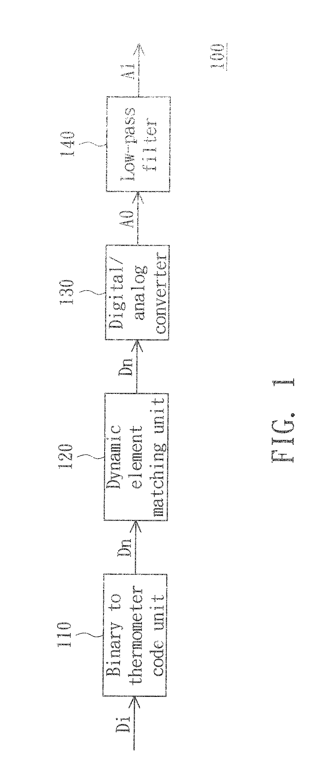
a digital/analog converter and digital/analog technology, applied in the direction of digital-analog convertors, transmission systems, instruments, etc., can solve the problems of increasing the cost and circuit size the complication of the binary to thermometer code unit and the dynamic element matching unit, and the complication of the digital/analog converting apparatus. to achieve the same accuracy of an analog signal, the circuit size and complication of the digital/analog
- Summary
- Abstract
- Description
- Claims
- Application Information
AI Technical Summary
Benefits of technology
Problems solved by technology
Method used
Image

Examples
embodiment one
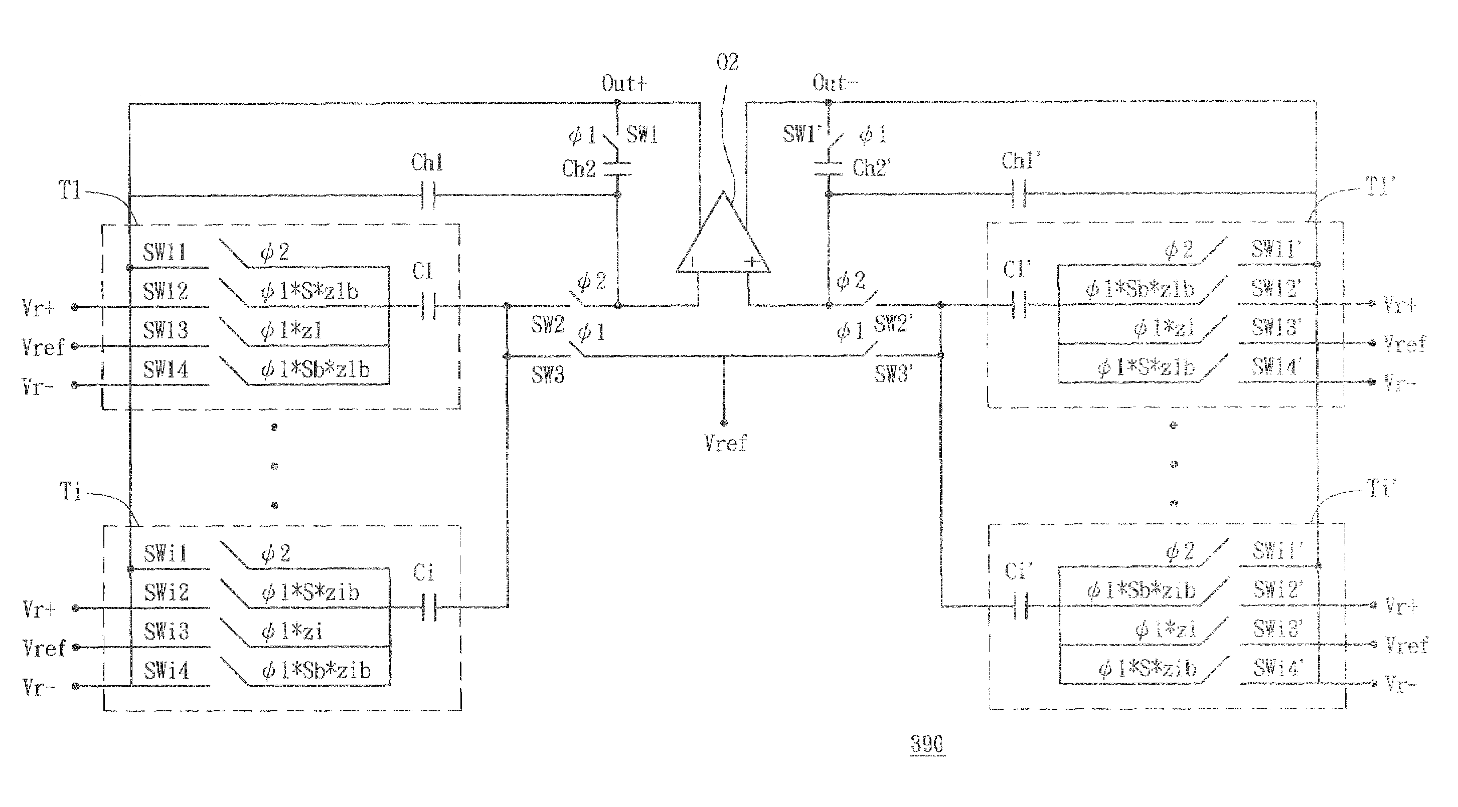
[0027]Referring to FIG. 3, a circuit diagram of a digital / analog converter according to a first embodiment of the invention is shown. A digital / analog converter 300 converts a digital signal Dn′ to an analog signal A0′. The digital / analog converter 300 includes a first filter Ch1, a second filter Ch2, switches SW1˜SW3, an operational amplifier O1, and conversion units T1 to Ti. The bit value and polarity of the digital signal Dn′ is inputted to each of the conversion units T1 to Ti. The first filter Ch1 and the second filter Ch2 are exemplified as capacitors in the description.
[0028]The operational amplifier O1 has an output terminal OUT, an inverse-phase input terminal and a non-inverse-phase input terminal and the non-inverse-phase input terminal is coupled to a reference voltage Vref. The first filter Ch1 has one end coupled to the output terminal OUT and the other end coupled to the inverse-phase input terminal of the operational amplifier O1. The second filter Ch2 has one end c...
example two
[0043]Referring to FIG. 6, a circuit diagram of a digital / analog converter according to a second embodiment of the invention is shown. A digital / analog converter 600 is only different in structure of the conversion units from the digital / analog converter 300. The digital / analog converter 600 includes conversion units 610(1) to 610(i).
[0044]The conversion unit 610(1) includes capacitors C11 and C12 and conversion switches 611˜616. The conversion unit 610(i) includes capacitors Ci1 and Ci2 and conversion switches 621˜626. In the following description, the conversion unit 610(i) is taken as an example for illustration.
[0045]The conversion switch 621 is controlled by the clock signal φ2, coupled to the output terminal OUT and the first end of the capacitor Ci1, and turned on in the second duration. The conversion switch 622 is controlled by a signal (φ1*S) and coupled between the first end of the capacitor Ci1 and the high voltage Vr+. The conversion switch 623 is controlled by a signal...
embodiment three
[0048]Referring to FIG. 7, a circuit diagram of a digital / analog converter according to a third embodiment of the invention is shown. A digital / analog converter 700 does not have the switch SW3 and is different only in the structure of the conversion units as compared to the digital / analog converter 300. The digital / analog converter 700 includes conversion units 710(1) to 710(i).
[0049]The conversion unit 710(1) includes a capacitor C71 and conversion switches 711 to 718. The conversion unit 710(i) includes capacitor C7i and conversion switches 721 to 728. In the following description, the conversion unit 710(i) is taken as an example for illustration.
[0050]The conversion switch 721 is controlled by the clock signal φ2 and coupled to the output terminal OUT and the first end of the capacitor C7i. The conversion switch 722 is controlled by the clock signal φ2 and coupled to the switch SW2 and the second end of the capacitor C7i. The conversion switches 721 and 722 are turned on in the...
PUM
 Abstract
Description
Claims
Application Information