Distributed switch architecture including a growth input/output bus structure

a switch and bus technology, applied in the field of switches, can solve problems such as inconvenience in adding functionality to conventional switches

Inactive Publication Date: 2008-10-14
SILICON LAB INC
View PDF7 Cites 40 Cited by
  • Summary
  • Abstract
  • Description
  • Claims
  • Application Information

AI Technical Summary

Problems solved by technology

Regardless of which type of switch is employed, it is often inconvenient to add functionality to conventional switches.

Method used


Image

  • Distributed switch architecture including a growth input/output bus structure
  • Distributed switch architecture including a growth input/output bus structure
  • Distributed switch architecture including a growth input/output bus structure

Examples


Embodiment Construction

)

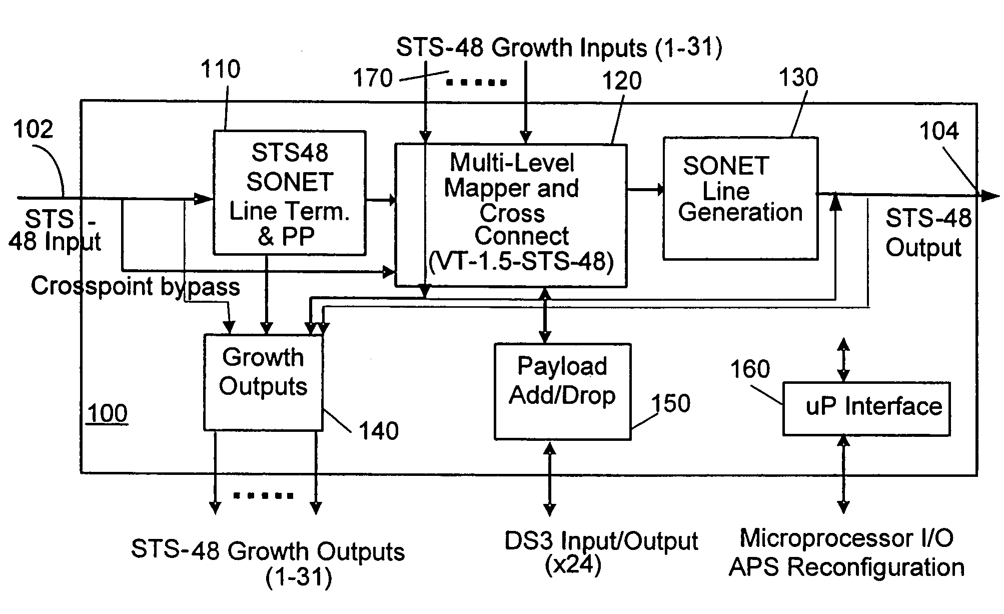
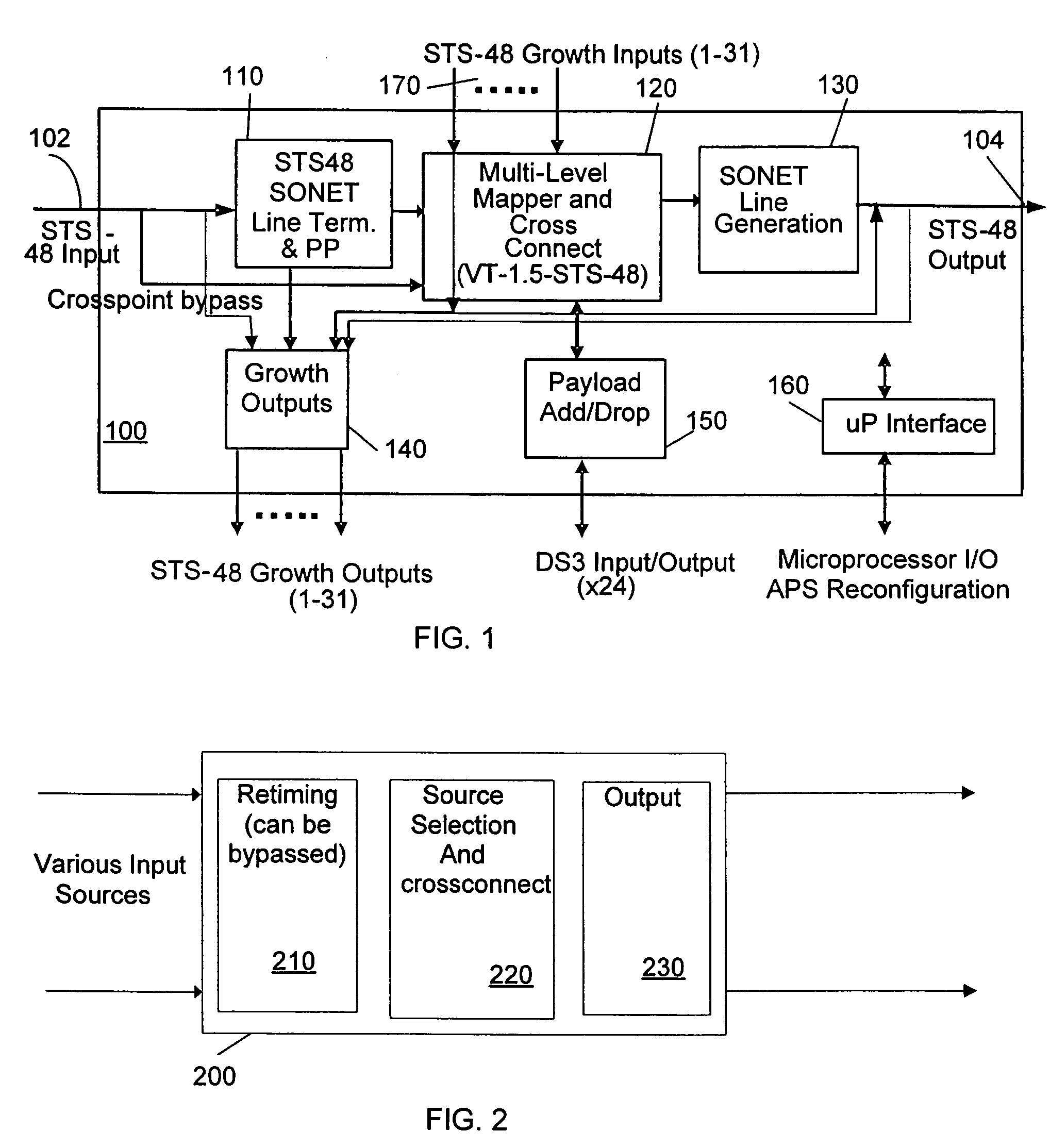
[0036]Referring first to FIG. 1, the integrated circuit cross-connect switch according to an embodiment of the present invention will be discussed, and is designated generally switch 100. Switch 100 includes line terminator and pointer processor (LTPP) 110, cross-connect 120, line generator 130, growth outputs 140, payload add / drop unit 150, microprocessor interface 160 and growth inputs 170. A portion of an STS-48 data stream is received at input 102 of switch 100, and is nominally provided to LTPP 110. LTPP 110 is connected to cross-connect 120, which maps and switches virtual tributaries (VTs) or other data streams embedded in the STS-48 input to the proper STS-48 output. Note that the output to which the data stream is mapped may be either output 104 of switch 100 or the output of another switch (not shown) connected to switch 100 via growth outputs 140.

[0037]The output of cross-connect 120 is connected to line generator 130, which reconstructs the data streams provided by cros...


PUM


Abstract

Multiple integrated circuits (ICs) are connected via growth inputs, into a network configuration, e.g. a ring network or a mesh network, to form a communications switch. Each IC includes additional growth inputs beyond those needed to form the switch. These growth inputs can be used to add additional functionality, e.g. protection or transmultiplexing, to the switch.

Description

BACKGROUND[0001]1. Field of the Invention[0002]This invention relates to telecommunications and more particularly to a switch utilized in a telecommunications network.[0003]2. Description of the Related Art[0004]Communications between different networks using various encoding techniques and multiplexing strategies has led to the development of a number of different switching technologies. These switching technologies are capable of receiving a signal composed of multiple embedded signals, and routing each individual embedded signal to different locations. For example, a common transmission protocol is the synchronous optical network protocol (SONET) specified by the American National Standards Institute (ANSI). SONET allows multiple data streams of different formats to be combined into a single high speed fiber optic synchronous data stream. Current switching technology breaks the SONET signal into its constituent parts, including the separate data streams. The separate data streams...

Claims


Application Information

Patent Timeline
Patent Type & Authority Patents(United States)
IPC IPC(8): H04L12/50H04Q11/00H02H9/00H04J3/16H04Q11/04
CPCH04J3/1611H04J2203/0012H04J2203/006
Inventor PEPENELLA, GERARD
Owner SILICON LAB INC
Why Eureka
Try Eureka