

Submarine observation apparatus and submarine observation system
a technology of observation apparatus and submarine, which is applied in the field of submarine observation apparatus and submarine observation system, can solve the problems of increasing the scale and cost of each of the plurality of submarine observation apparatus, increasing the temperature of the inside of the sealed housing of each of the plurality, and increasing the consumption of electric current, so as to improve the reliability suppress the increase in the scale and cost of the submarine observation apparatus, and the effect of high wavelength stability
- Summary
- Abstract
- Description
- Claims
- Application Information
AI Technical Summary
Benefits of technology
Problems solved by technology
Method used
Image

Examples
embodiment 1
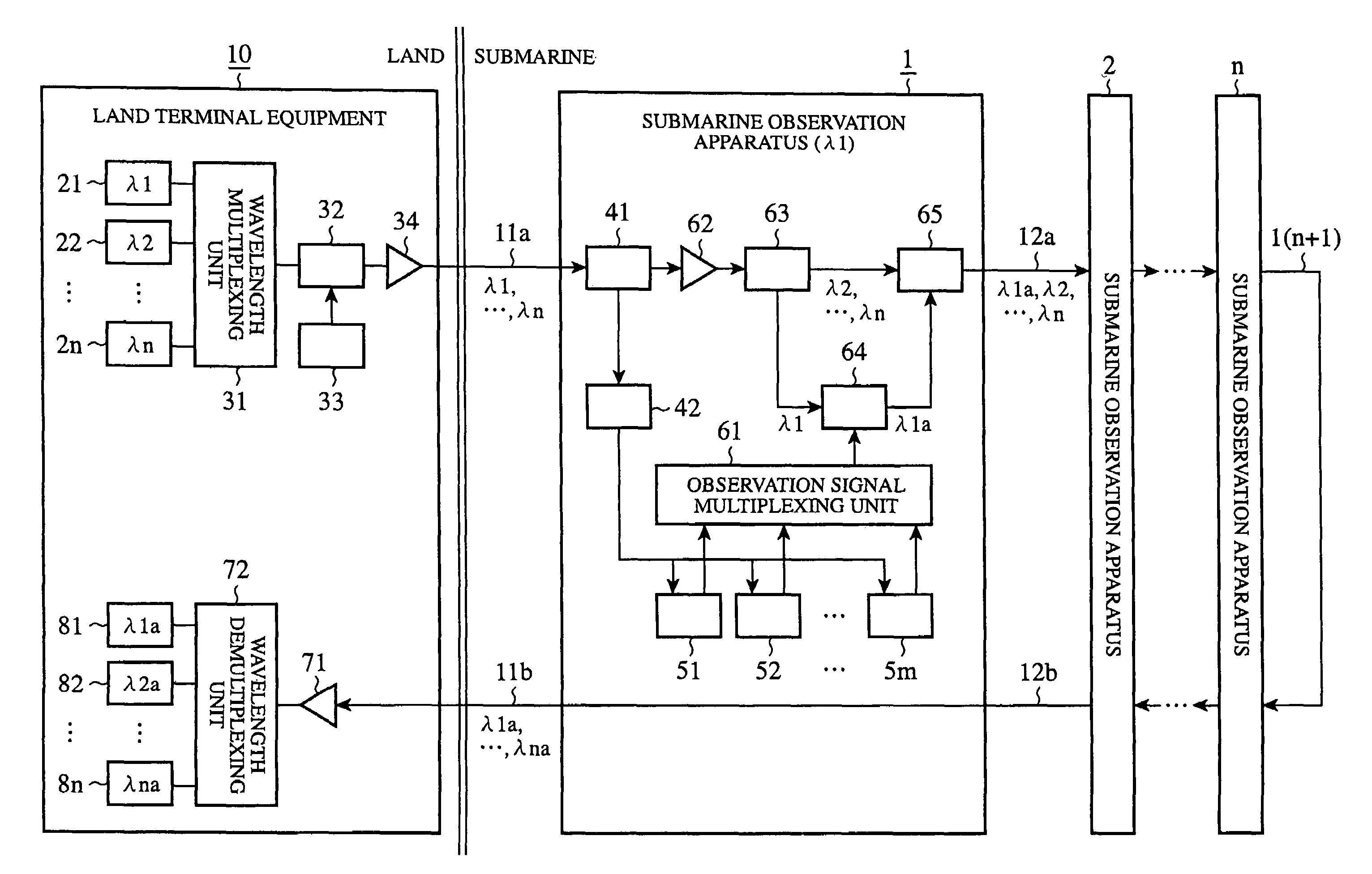
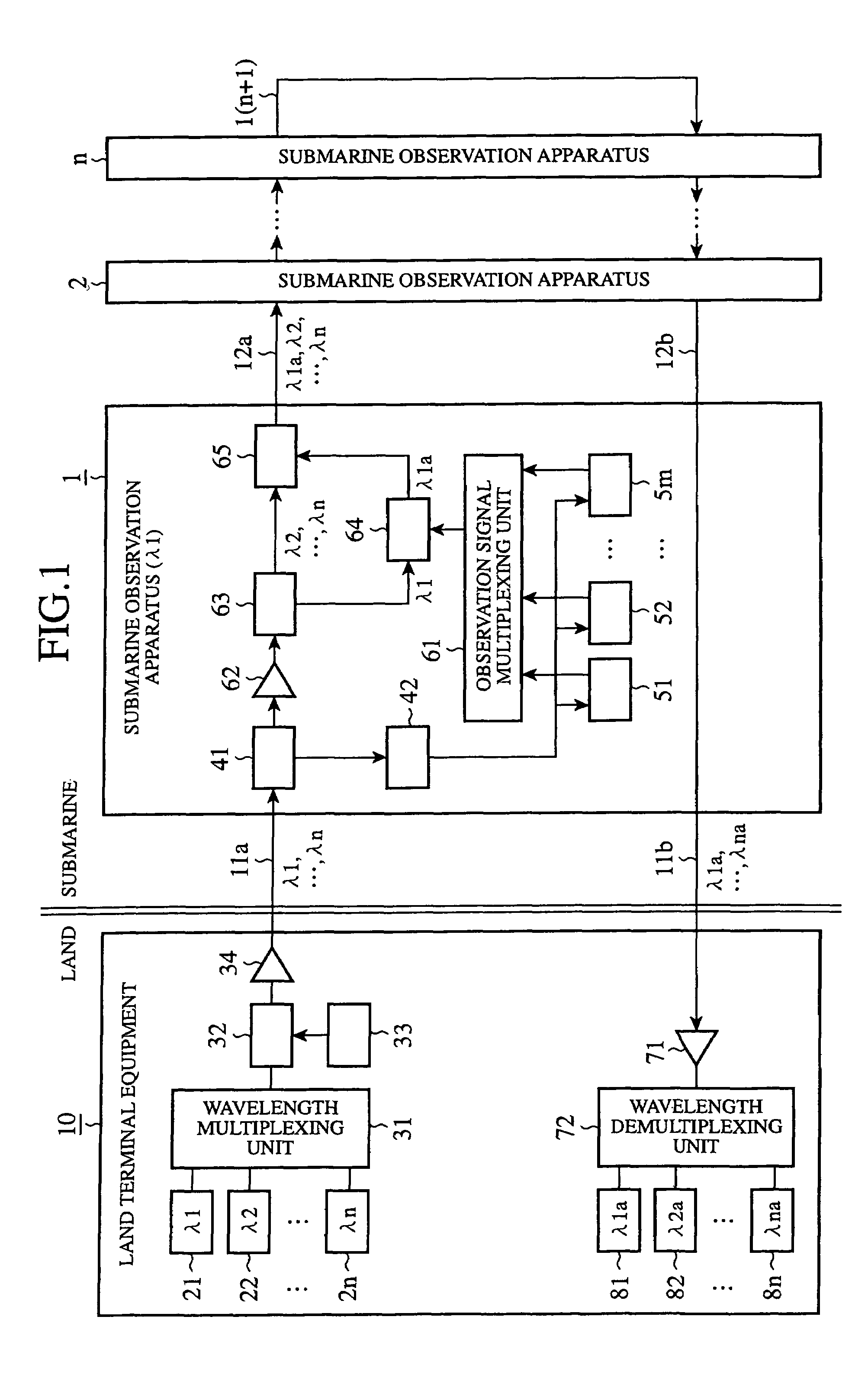
[0017]FIG. 1 is a block diagram showing a submarine observation system according to embodiment 1 of the present invention. The submarine observation system according to this embodiment 1 transmits multi-wavelength light having different wavelengths, which are respectively assigned in advance to a plurality of submarine observation apparatus, to a submarine optical cable according to a WDM (Wavelength Division Multiplexing) transmission method, and each of the plurality of submarine observation apparatus selectively branches a fixed-wavelength light signal assigned thereto, modulates the fixed-wavelength light signal selectively branched thereby with observation information detected thereby, and combines the modulated, fixed wavelength light signal and other multi-wavelength light signals to generate a composite light signal, and transmits it to land terminal equipment.
[0018]In the figure, the plurality of submarine observation apparatus 1 to n respectively placed at submarine observ...
embodiment 2
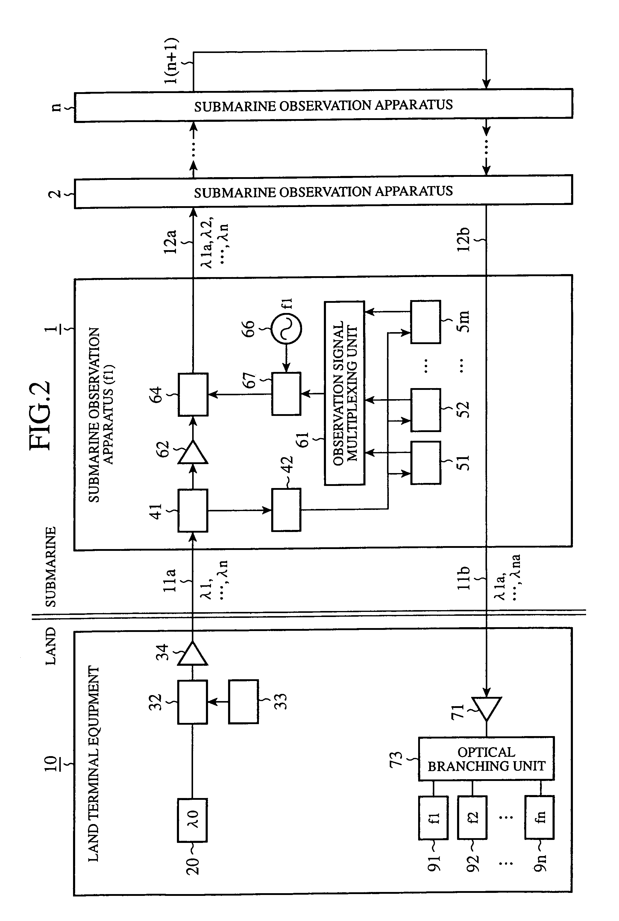
[0037]FIG. 2 is a block diagram showing a submarine observation system according to embodiment 2 of the present invention. While the submarine observation system according to above-mentioned embodiment 1 uses a WDM transmission method, as previously mentioned, the submarine observation system according to this embodiment 2 uses an optical SCM (Sub Carrier Multiplexing) method. According to this optical SCM method, carrier light from land terminal equipment is transmitted to a submarine optical cable as a light signal, different frequencies are assigned to a plurality of submarine observation apparatus, respectively, a subcarrier having a frequency which is assigned in advance to each of the plurality of submarine observation apparatus is modulated with observation information, the light signal transmitted from the land terminal equipment is further modulated with the subcarrier modulated with the observation information in each of the plurality of submarine observation apparatus, an...
embodiment 3
[0054]FIG. 3 is a block diagram showing a submarine observation system according to embodiment 3 of the present invention. In the submarine observation system according to above-mentioned embodiment 2, the land terminal equipment 10 transmits carrier light λ0 having a fixed wavelength to the plurality of submarine observation apparatus 1 to n respectively associated with different frequencies, and each of the plurality of submarine observation apparatus 1 to n modulates a subcarrier having a frequency assigned thereto with observation information, further modulates the intensity of an incoming light signal having the fixed wavelength with the modulated subcarrier wave, and outputs the intensity-modulated light signal so as to transmit observation information. In contrast, the submarine observation system according to this embodiment 3 uses a wavelength division multiplexing transmission method explained in above-mentioned embodiment 1, as well as an optical SCM method explained in a...
PUM
 Abstract
Description
Claims
Application Information