Method and apparatus for objective measurement of noise

a technology of objective measurement and noise, applied in the field of methods and apparatus for measuring noise, can solve the problems of not objectively measuring the sound level, not analysing, and specifically undesired or unwanted sounds, so as to reduce and correct and eliminate the undesired sound level or noise

Active Publication Date: 2008-10-14
FORD MOTOR CO
View PDF34 Cites 21 Cited by
  • Summary
  • Abstract
  • Description
  • Claims
  • Application Information

AI Technical Summary

Benefits of technology

[0010]In accordance with the present invention, the recorded sound level and correspondingly objective metric value obtained are saved as raw data by the data acquisition apparatus. In addition, the operator or technician enters information into the data acquisition apparatus related to the diagnosis and repair. The diagnoses and repair information is entered using the customer concern codes or warranty parameters. Thus, information retrieved from the database relating to the products or assemblies tested is available to prepare charts and graphs relating to the source of the undesired sound level or noise; i.e., squeaks or rattles, along with the repair undertaken to correct and eliminate the undesired sound level or noise. In accordance with a further aspect of the invention, information relating to possible causes of the undesired sound level or noise is transmitted to the assembly or fabrication line and when possible, suggestions are made that may help to reduce the undesired sound or noise level.

Problems solved by technology

Operation of a motor vehicle may result in vibrations in the vehicle that can cause noise, or more specifically undesired or unwanted sounds.
They do not objectively measure the sound level, nor do they analyze the data obtained by the relating the sound level to the cause thereof.

Method used


Image

  • Method and apparatus for objective measurement of noise
  • Method and apparatus for objective measurement of noise
  • Method and apparatus for objective measurement of noise

Examples


Embodiment Construction

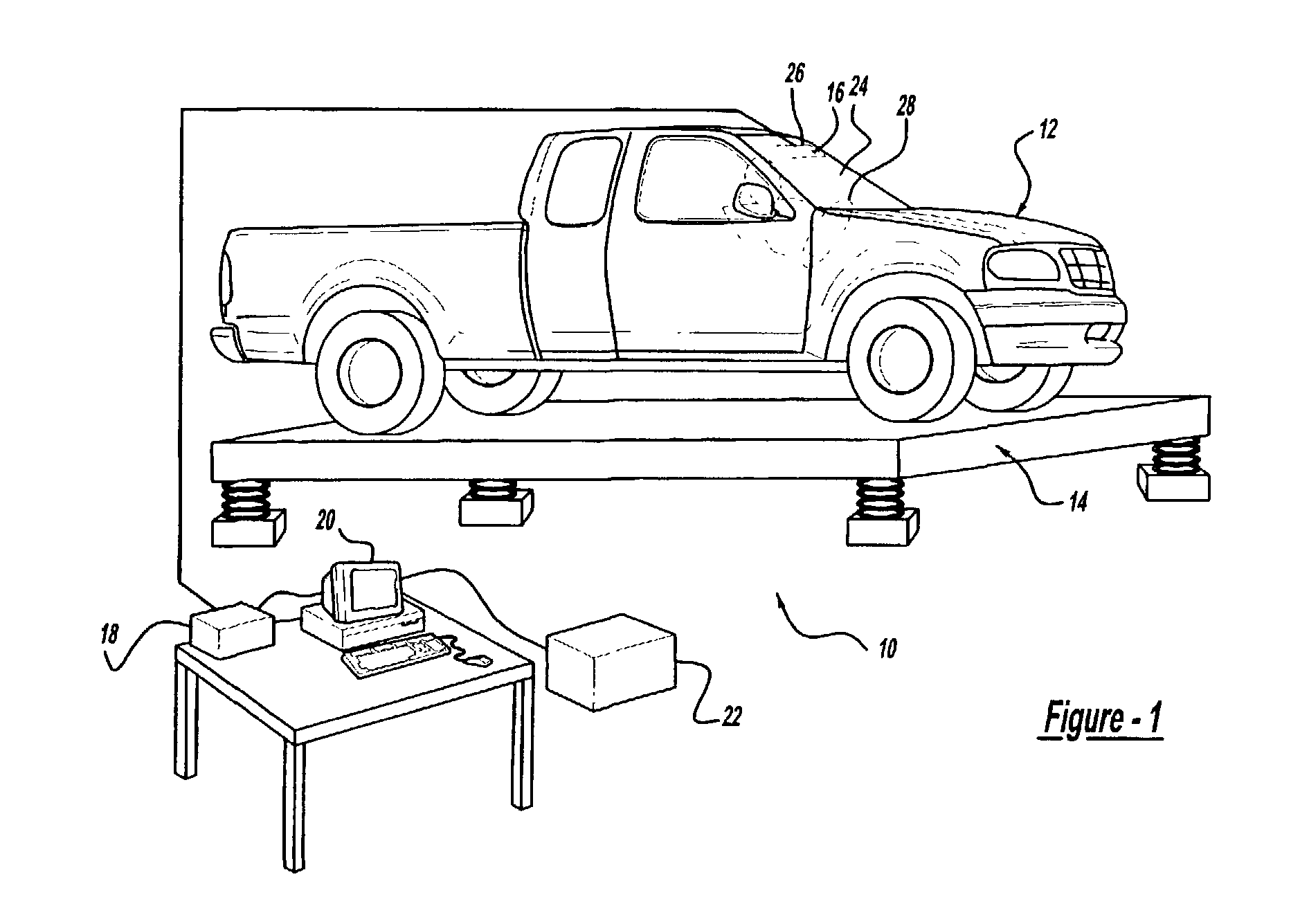
[0017]FIG. 1 illustrates an apparatus or system 10 for objectively monitoring the level of sound in a vehicle 12 occurring when the vehicle 12 is vibrated to simulate on road operation according to one embodiment of the present invention. While shown for use with a vehicle 12, it should be understood that the method disclosed herein is suitable for use with any product or assembly, including any vehicle components or other products, having quality concerns relating to noise or sound levels. For instance, the method disclosed herein is useful for objectively measuring the noise; i.e. squeak and rattle of vehicle components separate and independent of the vehicle. Accordingly, evaluation of individual components for undesired sound or noise levels may take place prior to assembly in a vehicle.

[0018]As shown in FIG. 1, the vehicle 12 is placed on a vibration generator, seen generally at 14. Upon activation, the vibration generator 14, commonly referred to as a “four-poster,” shakes or ...


PUM


Abstract

A method of objectively and subjectively monitoring noise and correspondingly level or loudness thereof in a product or assembly. The method includes placing a product on the vibration generator. Activating the vibration generator to move or shake the product to simulate usage conditions. A sound recording instrument measures and records the noise emitted by the product or assembly. Comparing an objective metric computed from the recorded noise with a threshold metric. Evaluating the vehicle to determine the noise source when the objective metric exceeds the threshold metric. Saving the objective metric along with the information relating to the source of the noise and necessary repairs for further evaluation and statistical analysis.

Description

BACKGROUND OF INVENTION[0001]1. Field of the Invention[0002]The present invention relates generally to a method and apparatus for measuring noise and correspondingly the level or loudness thereof in a product, such as a motor vehicle, during use; and more particularly, to a method for objectively monitoring and measuring the noise level and comparing the noise level to a known reference value.[0003]2. Background of the Invention[0004]As part of ongoing quality concerns, motor vehicle manufacturers monitor and inspect their products during and after the manufacturing process. One method of tracking vehicle quality is the use of warranty coding parameters. These parameters typically include a list of vehicle systems, individual components associated with the systems and a list of descriptors; i.e., standard descriptive words used to describe any problems or remedial action taken with respect to a particular problem. Utilizing a standard set of codes, aids in evaluating vehicle quality...

Claims


Application Information

Patent Timeline
Patent Type & Authority Patents(United States)
IPC IPC(8): G06F11/30G01M17/007
CPCG01M17/007
Inventor CHARETTE, FRANCOISJUNEJA, VIKASVENKATAPPA, SUHASHOOKER, RICK S.QUAGLIA, RONALD LOUISBLOMMER, MICHAEL ALANMASKILL, MARK NORMAN
Owner FORD MOTOR CO
Why Eureka
Try Eureka