Kinetic energy penetrator and method of using same

a technology of kinetic energy and penetrators, which is applied in the direction of electrical fuzes, applications, lighting and heating apparatus, etc., to achieve the effect of less aerodynamic drag and higher aerodynamic stability

Active Publication Date: 2008-10-21
LOCKHEED MARTIN CORP
View PDF24 Cites 4 Cited by
  • Summary
  • Abstract
  • Description
  • Claims
  • Application Information

AI Technical Summary

Benefits of technology

[0014]The present invention provides significant advantages, including: (1) providing a vehicle operably associated with the present invention to exhibit a higher degree of aerodynamic and / or hydrodynamic stability; (2) providing a vehicle operably associated with the present invention to hold more propellant and, thus, reach targets at greater distances; (3) providing a vehicle operably associated with the present invention having less aerodynamic drag.

Problems solved by technology

Such a conventional configuration, however, presents several problems.

Method used


Image

  • Kinetic energy penetrator and method of using same
  • Kinetic energy penetrator and method of using same
  • Kinetic energy penetrator and method of using same

Examples


Embodiment Construction

[0032]Illustrative embodiments of the invention are described below. In the interest of clarity, not all features of an actual implementation are described in this specification. It will of course be appreciated that in the development of any such actual embodiment, numerous implementation-specific decisions must be made to achieve the developer's specific goals, such as compliance with system-related and business-related constraints, which will vary from one implementation to another. Moreover, it will be appreciated that such a development effort might be complex and time-consuming but would nevertheless be a routine undertaking for those of ordinary skill in the art having the benefit of this disclosure.

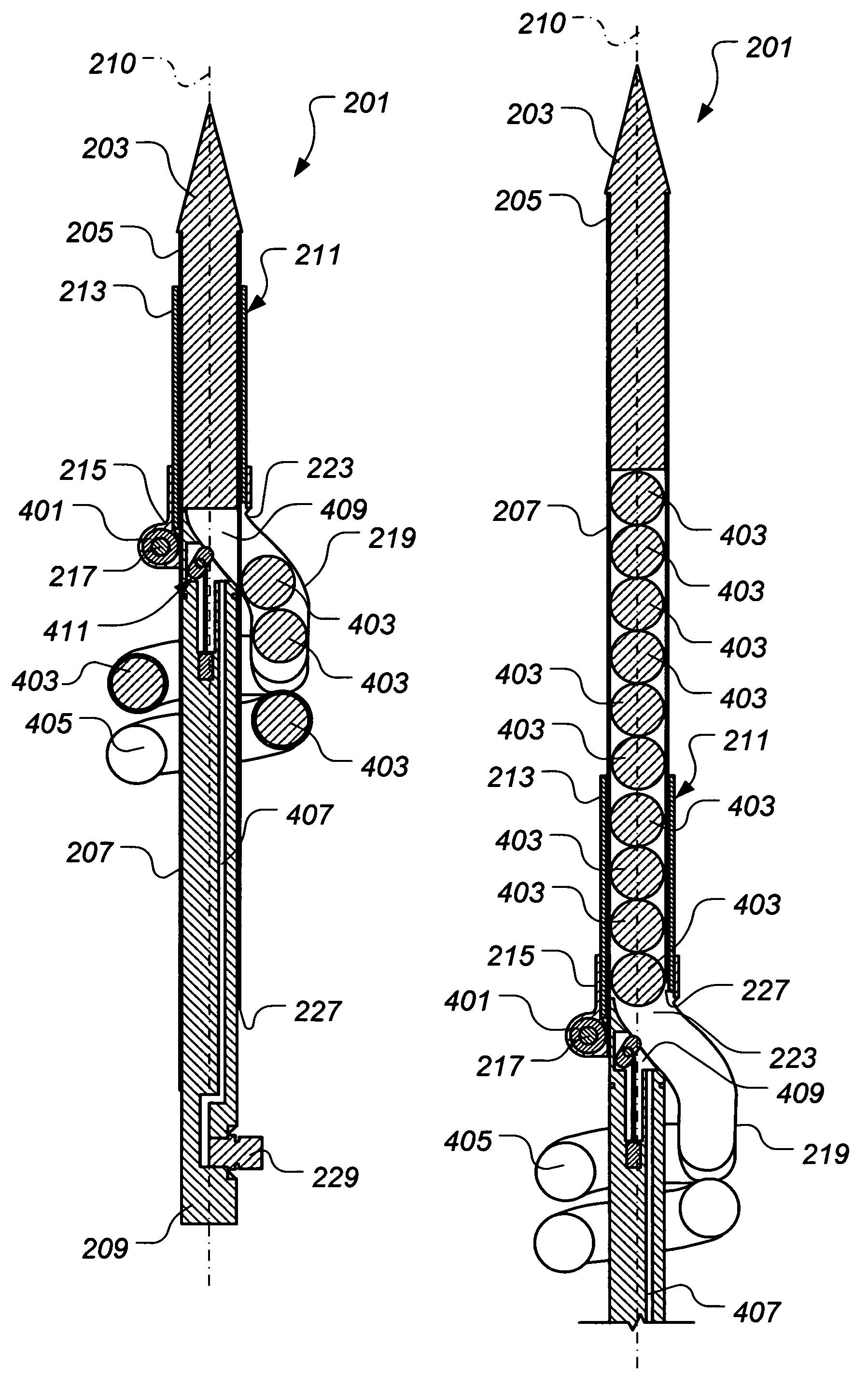
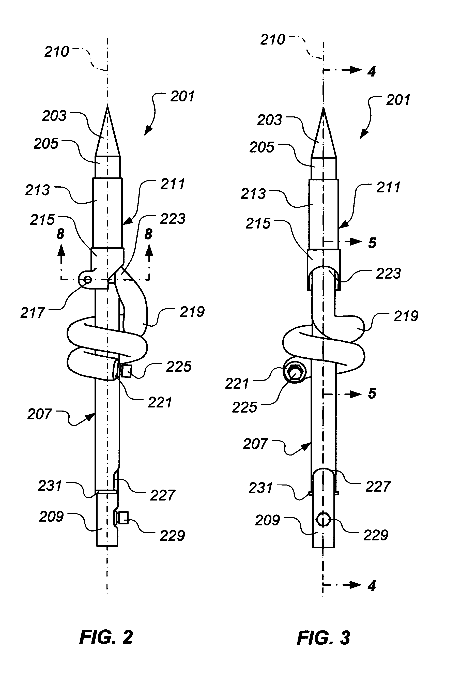
[0033]The present invention represents a kinetic energy penetrator adapted to be operably associated with an airborne or waterborne vehicle, such as a projectile, a rocket, a missile, a torpedo, a drone, or the like. In a preferred embodiment, the kinetic energy penetrator compris...


PUM


Abstract

A kinetic energy penetrator includes a plurality of penetrator segments, a penetrator segment sleeve for storing the plurality of penetrator segments, and means for moving the plurality of penetrator segments from the penetrator segment sleeve to locations substantially aligned along an axis of attack. A method includes storing a plurality of penetrator segments away from an axis of attack and moving the plurality of penetrator segments to locations substantially aligned along the axis of attack. A vehicle includes a body and a kinetic energy penetrator disposed in a forward portion of the vehicle. The kinetic energy penetrator includes a plurality of penetrator segments, a penetrator segment sleeve for storing the plurality of penetrator segments, and means for moving the plurality of penetrator segments from the penetrator segment sleeve to locations substantially aligned along an axis of attack.

Description

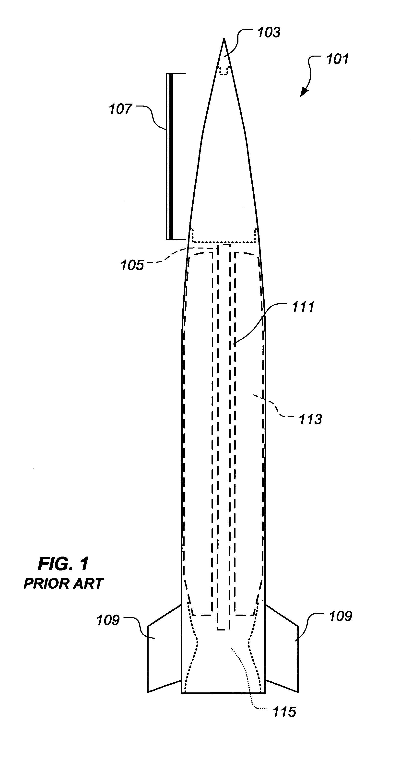
BACKGROUND[0001]1. Field of the Invention[0002]The present invention relates to kinetic energy penetrators. In particular, the present invention relates to a kinetic energy penetrator having movable penetrator segments and a method for using the penetrator.[0003]2. Description of Related Art[0004]Generally, a kinetic energy weapon uses kinetic energy, rather than, for example, explosive energy, to defeat a target. A conventional kinetic energy weapon, such as a kinetic energy projectile 101 shown in FIG. 1, typically includes a precursor 103 and penetrator rod 105, each comprising a relatively dense material, such as tungsten, steel, depleted uranium, or the like. When kinetic energy projectile 101 reaches a target, precursor 103 generates an opening, or at least an area of reduced strength, in the target through which penetrator rod 105 travels as kinetic energy projectile 101 continues to impact the target. Penetrator rod 105, whether intact or fragmented, impacts materiel and / or ...

Claims


Application Information

Patent Timeline
Patent Type & Authority Patents(United States)
IPC IPC(8): F42B12/58F42B30/00
CPCF42B5/045F42B10/02F42B10/38F42B12/06
Inventor TURNER, MARK A.GREISSER, WILLIAM R.
Owner LOCKHEED MARTIN CORP
Why Eureka
Try Eureka