Surface light source device and liquid crystal display assembly

a liquid crystal display and surface light source technology, applied in the construction details of electrical appliances, lighting and heating appliances, instruments, etc., can solve the problems of increasing cost and complexity of the structure of the surface light source device, and achieve the effects of improving cooling efficiency, low cost, and favorable heat radiation characteristics

Active Publication Date: 2008-10-21
SATURN LICENSING LLC
View PDF8 Cites 29 Cited by
  • Summary
  • Abstract
  • Description
  • Claims
  • Application Information

AI Technical Summary

Benefits of technology

[0007]According to the structure of the related art, the heat pipe and the heat sink are attached to the surface light source device as independent components. This adds complexity to the structure of the surface light source device, leading to an increase in cost.
[0008]Accordingly, it is desirable to provide a liquid crystal display assembly of superior image quality which includes a surface light source device that can provide favorable heat radiation characteristics at low cost. Further, it is also desirable to provide a surface light source device that can provide favorable heat radiation characteristics at low cost and suppress luminance or color variations.
[0013]In the surface light source device constituting the liquid crystal display assembly according to an embodiment of the present invention, and the surface light source device according to an embodiment of the present invention (hereinafter, these will often be generically referred to as “the surface light source device according to an embodiment of the present invention”) including the various preferred modes and configurations as described above, the light source that illuminates the liquid crystal display is arranged on the bottom plate. The light source may either be directly attached to the bottom plate or indirectly attached to the bottom plate via another component. For example, a configuration can be adopted in which the light source is attached onto a plate-shaped member formed of a metallic material such as aluminum, copper, or stainless steel, and this plate-shaped member is fixed onto the bottom plate. The number of light sources may be selected as appropriate in accordance with the size, structure, and the like of the surface light source device. In a configuration where a plurality of light sources are arranged, the plurality of light sources are arranged at a spacing from each other, with each light source being arranged at the boundary between the first fin portion and the bottom plate (more specifically, in the portion of the bottom plate at the boundary between the first fin portion and the bottom plate or in the vicinity of the boundary). In this case, either all or some of the bottom surfaces of the respective light sources (that is, the surfaces on the radiator fin side) may face the bottom plate. By adopting the configuration in which each light source is arranged at the boundary between the first fin portion and the bottom plate, heat generated by each light source is efficiently transmitted to the first fin portion, thereby enabling efficient cooling of the light source.
[0024]In the surface light source device constituting the liquid crystal display assembly according to an embodiment of the present invention, and the surface light source device according to an embodiment of the present invention, the radiator fins are formed integrally with the bottom plate constituting the housing, and hence there is no need to attach the radiator fins to the housing or the like as independent components. Further, a passage for air is secured in both of the directions parallel to and perpendicular to the first fin portion, thereby achieving an improvement in cooling efficiency. Furthermore, since the second fin portion is formed by bending a part of the first fin portion in a direction away from the liquid crystal display, the second fin portion can be arranged on the lower temperature side. It is thus possible to obtain a liquid crystal display assembly including a surface light source device that can provide favorable heat radiation characteristics at low cost, and a surface light source device that can provide favorable heat radiation characteristics at low cost and suppress luminance or color variations.

Problems solved by technology

This adds complexity to the structure of the surface light source device, leading to an increase in cost.

Method used


Image

  • Surface light source device and liquid crystal display assembly
  • Surface light source device and liquid crystal display assembly
  • Surface light source device and liquid crystal display assembly

Examples


Embodiment Construction

[0034]The present invention will now be described by way of its embodiments with reference to the drawings.

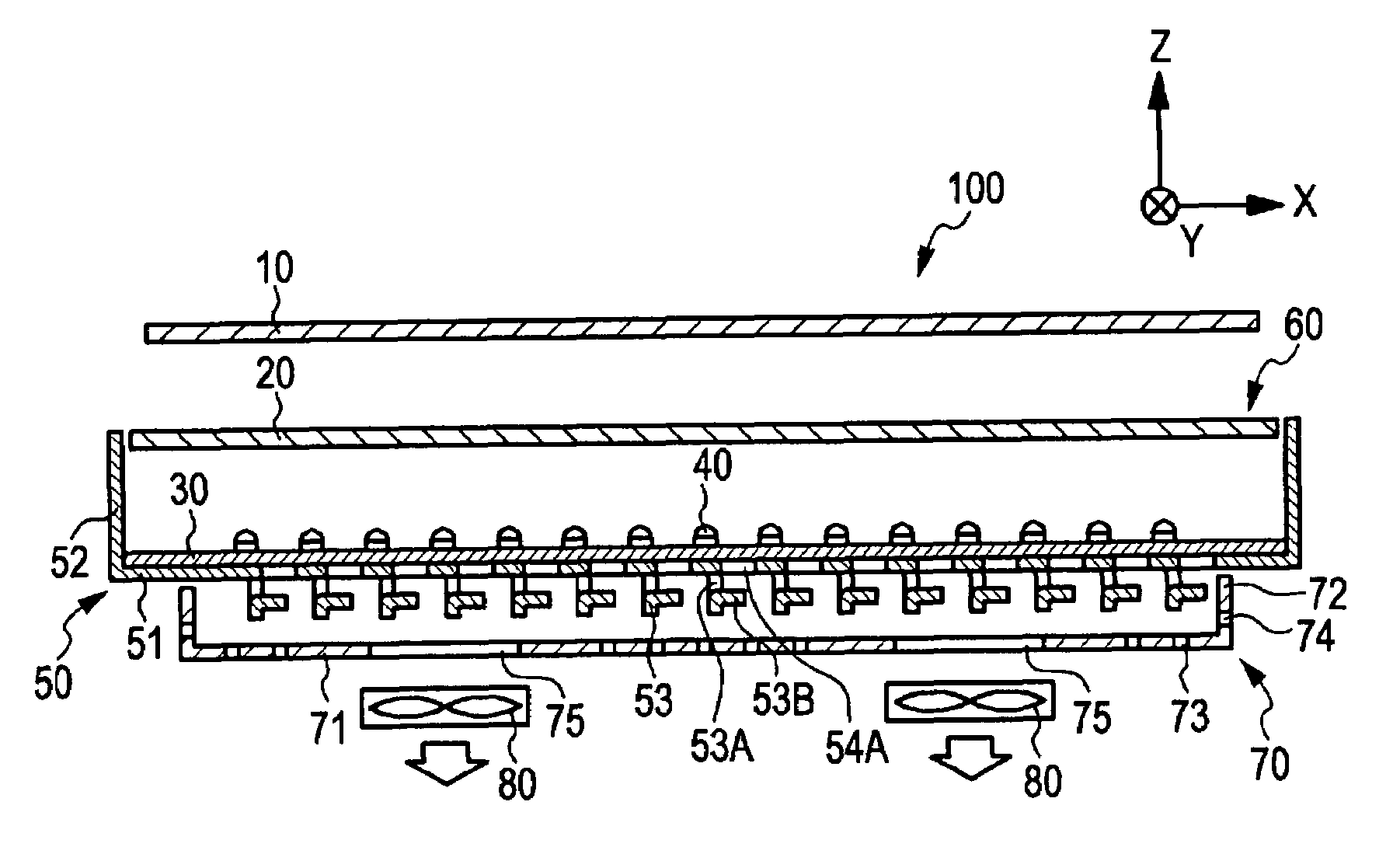
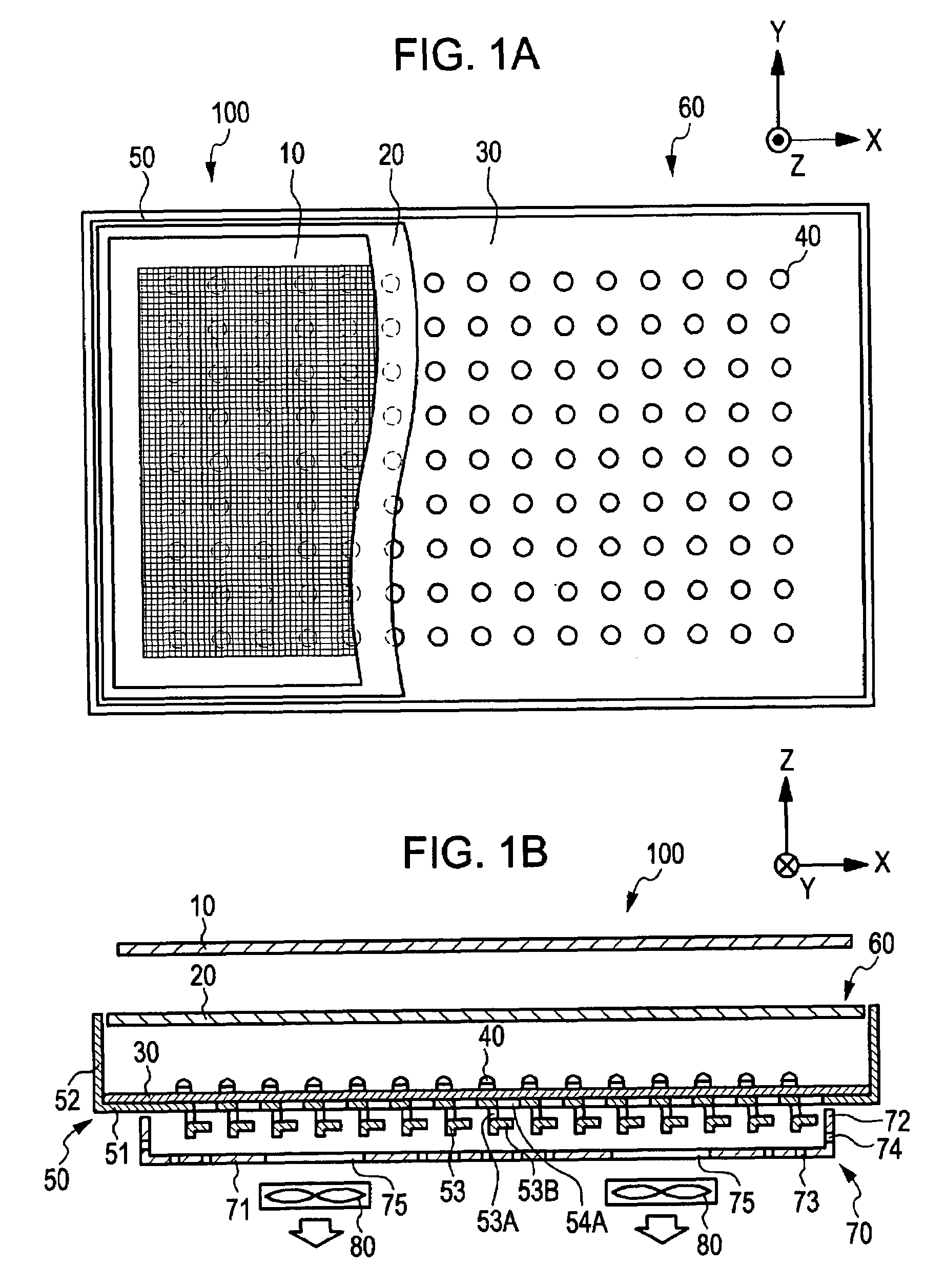
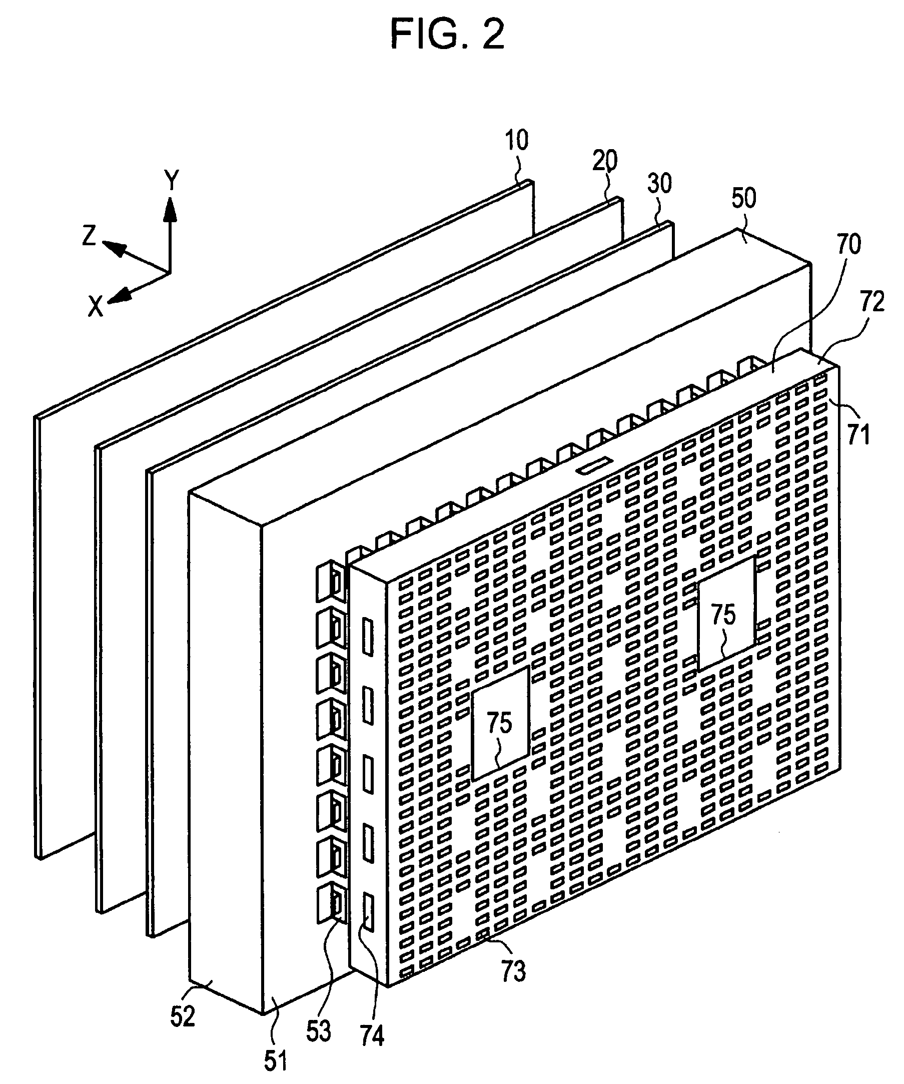
[0035]An embodiment of the present invention relates to a liquid crystal display assembly and a surface light source device. FIG. 1A is a schematic conceptual view of a liquid crystal display assembly 100 and a surface light source device 60 according to this embodiment. FIG. 1B is a schematic view, partly in section, of the liquid crystal display assembly 100 and the surface light source device 60 according to this embodiment. In FIG. 1B, the hatching of the liquid crystal display 10 and a diffuser plate 20 is omitted. FIG. 2 is a schematic exploded perspective view of the liquid crystal display assembly 100 and the surface light source device 60. In FIG. 2, blower units 80 are omitted from the drawing for the sake of convenience.

[0036]The liquid crystal display assembly 100 according to this embodiment includes:

[0037](a) the liquid crystal display 10; and

[0038](b) the surface...


PUM


Abstract

A liquid crystal display assembly includes a liquid crystal display, and a surface light source device that illuminates the liquid crystal display from a back surface. The surface light source device includes a housing including a bottom plate, a light source that is arranged on the bottom plate and illuminates the liquid crystal display, and a plurality of radiator fins arranged at a spacing from each other. Each of the radiator fins includes a first fin portion formed by bending a part of the bottom plate in a direction away from the liquid crystal display, the first fin portion extending substantially perpendicularly to the bottom plate, and a second fin portion formed by bending a part of the first fin portion in a direction away from the liquid crystal display, the second fin portion extending substantially parallel to the bottom plate.

Description

CROSS REFERENCES TO RELATED APPLICATIONS[0001]The present invention contains subject matter related to Japanese Patent Application JP 2006-155034 filed in the Japanese Patent Office on Jun. 2, 2006, the entire contents of which are incorporated herein by reference.BACKGROUND OF THE INVENTION[0002]1. Field of the Invention[0003]The present invention relates to a surface light source device and a liquid crystal display assembly.[0004]2. Description of the Related Art[0005]In a liquid crystal display, liquid crystal itself does not emit light. Thus, for example, a so-called direct-type surface light source device (backlight) that radiates light to a liquid crystal display is arranged on the back surface of the liquid crystal display. By causing liquid crystal cells constituting each pixel to operate as a kind of optical shutter (light valve), that is, by controlling the light transmittance of each pixel, the optical transmittance of light (for example, white light) emitted from the sur...

Claims


Application Information

Patent Timeline
Patent Type & Authority Patents(United States)
IPC IPC(8): F21V29/00
CPCG02F1/133608H05K7/20972G02F2001/133628G02F1/133628G02F1/1335G02F1/1333
Inventor AOKI, TOMIOMORITA, MASAYOSHI
Owner SATURN LICENSING LLC
Why Eureka
Try Eureka