Electromagnetic actuator using permanent magnets

a technology of permanent magnets and actuators, applied in the direction of magnets, magnets, propulsion systems, etc., can solve the problems of no room for design modification to alleviate structural limitations, and the placement of the magnetic poles of the magnets has various limitations, so as to achieve the effect of increasing efficiency and excessive positional changes

Inactive Publication Date: 2008-10-21
GK BRIDGE 1
View PDF11 Cites 24 Cited by
  • Summary
  • Abstract
  • Description
  • Claims
  • Application Information

AI Technical Summary

Benefits of technology

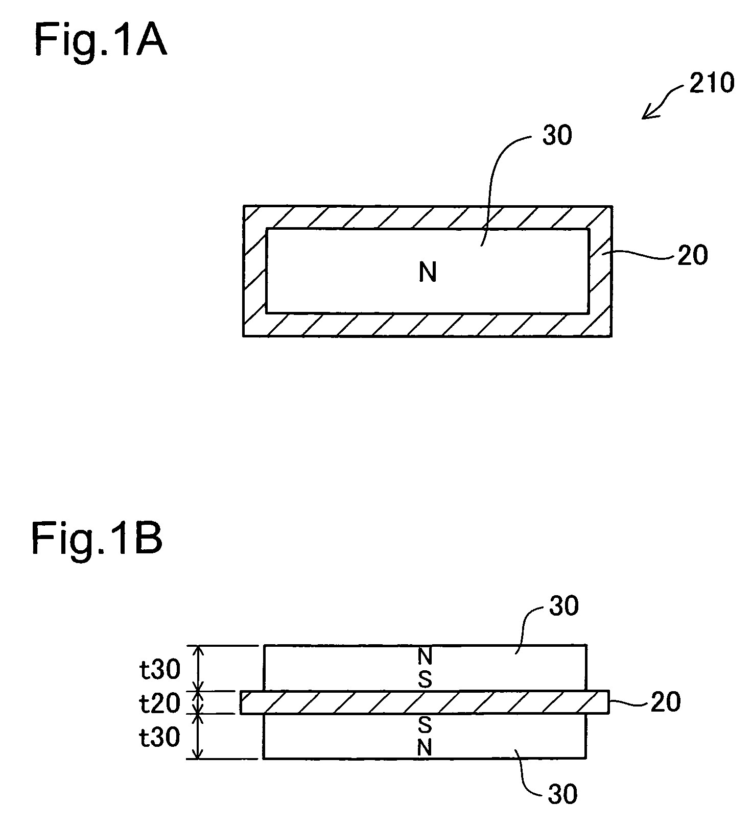
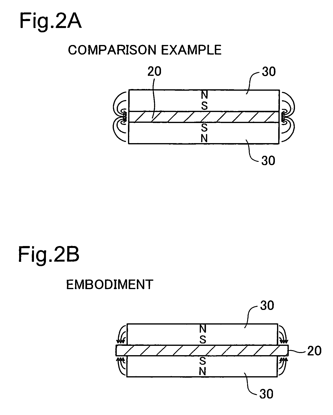
[0009]In this first actuator, because first and second magnets that are pulled onto either side of the plate portion of the yoke member such that identical poles face each other across the plate portion of the yoke member, a construction in which identical magnetic poles face various directions outward from the yoke member can be obtained. As a result, an actuator that efficiently uses the magnet flux generated by these magnets can be constructed. Moreover, because the first and second magnets are pulled onto the same plate portion, identical magnetic pole can face the two opposite directions facing outward from the center of the plate portion. In addition, the pulling force between the magnets and the yoke member can be made larger than the repulsion force between the first and second magnets because the main surfaces of the plate portion of the yoke member are set to have a size which encompasses respective surfaces of the first and second magnets that face the plate portion.
[0015]In this second actuator, because first and second magnets that are pulled onto either side of the plate portion of the yoke member such that identical poles face each other across the plate portion of the yoke member, a construction in which identical magnetic poles face various directions outward from the yoke member can be obtained. As a result, an actuator that efficiently uses the magnet flux generated by these magnets can be constructed. Moreover, because the first and second magnets are pulled onto the same plate portion, identical magnetic pole can face the two opposite directions facing outward from the center of the plate portion. In addition, the pulling force between the magnets and the yoke member can be made larger than the repulsion force between the first and second magnets because the yoke member is constructed so that the plate portion has a protrusion portion protruding from the first and second magnets when viewed along a direction of thickness of the plate portion.
[0017]In this third actuator, because first and second magnets that are pulled onto either side of the yoke member such that identical poles face each other across the yoke member, a construction in which identical magnetic poles face various directions outward from the yoke member can be obtained. As a result, an actuator that efficiently uses the magnet flux generated by these magnets can be constructed.PREFERRED FEATURES OF THE INVENTION
[0021]According to this construction, because the electromagnetic coil is driven using any of the three current values, simple control may be realized.
[0023]According to this construction, the current value can be gradually increased after the sign of the deviation changes, and therefore excessive positional change can be prevented when the deviation is near zero.
[0025]According to this construction, the rate of increase of the current value after the sign of the deviation changes can be further reduced, and therefore excessive positional change when the deviation is near zero can be prevented with increased efficiency.

Problems solved by technology

With an electromagnetic actuator that uses permanent magnets, electromagnetic force is generated using the N and S poles of the magnets, but the problem arises that, when constructing the electromagnetic actuator, various limitations exist in connection with the placement of the magnetic poles of the magnets (i.e., due to the existence of the N and S poles).
However, in the conventional art, it has been acknowledged that there is no room for design modification to alleviate the structural limitations in connection with the placement of the magnetic poles.

Method used


Image

  • Electromagnetic actuator using permanent magnets
  • Electromagnetic actuator using permanent magnets
  • Electromagnetic actuator using permanent magnets

Examples


first embodiment

B-1. First Embodiment of Control Device

[0092]FIG. 16 shows a change in current during position control in connection with a first embodiment of an actuator mechanism control device. In the first embodiment, where the actuator mechanism 100 (FIGS. 4A-4C) is to be moved in the leftward direction, a constant positive current value Ip is impressed to the electromagnetic coil unit 110. Where the actuator mechanism 100 is to be moved in the rightward direction, on the other hand, a constant negative current In is impressed to the electromagnetic coil unit 110. In this way, according to the control device of the first embodiment, the controlled variable (the position of the actuator mechanism) and the manipulated variable (the current value impressed to the electromagnetic coil unit 110) are set to have a nonlinear relationship. Therefore, as described below, position control is executed using a principle different from PID control. The reason that the position and the current value are se...

second embodiment

B-2. Second Embodiment of Control Device

[0104]FIG. 22 is a block diagram showing the internal construction of a current value determination unit 450a of a second embodiment. FIG. 23 is a timing chart showing the operation of the control device of the second embodiment. The construction of the second embodiment differs from that of the first embodiment solely in regard to the construction of the current determination unit, and is otherwise identical thereto.

[0105]This current value determination unit 450a has a deviation limit value storage unit 600, a three-value determination unit 602, a current value table 604, a counter 606, a coefficient generator 608, a multiplier 610 and an integrator (accumulator) 612. The three-value determination unit 602, like the three-value determination unit 452 shown in FIG. 19, outputs three deviation sign signals UP, EQU and DOWN, and supplies the deviation A4 to the current value table 604. The three-value determination unit 602 also has the functio...

third embodiment

B-3. Third Embodiment of Control Device

[0111]FIG. 25 is a block diagram showing the construction of a control device of a third embodiment. FIG. 26 is a timing chart pertaining to the operation of the control device of the third embodiment. This control device 400a differs from the control device of the first embodiment (FIG. 17) in that it has the current value determination unit 450a of the second embodiment (FIG. 22) in place of the current value determination unit 450 (FIG. 17), and includes a polarity reduction unit 620 between the current value determination unit 450a and the drive signal generator 460. In other words, the control device of the third embodiment comprises the control device of the second embodiment to which a polarity reduction unit 620 is added.

[0112]FIG. 27 is a block diagram showing the internal construction of the polarity reduction unit 620. The polarity reduction unit 620 has an up / down continuous determination unit 622, a counter 624 and a reduction coef...


PUM


Abstract

An actuator mechanism having a different magnet polarity arrangement than the conventional mechanisms is provided. The actuator mechanism 100 has a magnet unit 210 that includes magnets 30 and an electromagnetic coil unit 110 that includes an electromagnetic coil. the relative positions of the magnet unit 210 and the magnetic coil unit 110 can change. The magnet unit 210 includes a yoke member 20 and two or more magnets 30. The two magnets 30 are pulled toward the yoke member 20 in the state where identical poles face each other across the yoke member 20.

Description

CROSS-REFERENCE TO RELATED APPLICATIONS[0001]The present application claims the priority based on Japanese Patent Application No. 2005-214838 filed on Jul. 25, 2005, the disclosure of which is hereby incorporated by reference in its entirety.BACKGROUND OF THE INVENTION[0002]1. Field of the Invention[0003]The present invention relates to an electromagnetic actuator that uses permanent magnets.[0004]2. Description of the Related Art[0005]Electromagnetic actuators that use permanent magnets have been widely employed (see JP2002-90705A, and JP2004-264819A, for example).[0006]With an electromagnetic actuator that uses permanent magnets, electromagnetic force is generated using the N and S poles of the magnets, but the problem arises that, when constructing the electromagnetic actuator, various limitations exist in connection with the placement of the magnetic poles of the magnets (i.e., due to the existence of the N and S poles). However, in the conventional art, it has been acknowledged...

Claims


Application Information

Patent Timeline
Patent Type & Authority Patents(United States)
IPC IPC(8): H02K41/00
CPCH01F7/066H01F7/081H01F7/1615
Inventor TAKEUCHI, KESATOSHI
Owner GK BRIDGE 1
Why Eureka
Try Eureka