Enhancement-depletion Darlington device

a darlington amplifier and enhancement technology, applied in the field of amplifiers, can solve the problems of reducing the output power capability of darlington amplifiers, reducing the linear output capability, and limiting the output p1db and ip3 voltage, so as to reduce the knee voltage, improve linear output capability, and reduce the output power. the effect of darlington

Active Publication Date: 2008-10-21
QORVO US INC
View PDF8 Cites 32 Cited by
  • Summary
  • Abstract
  • Description
  • Claims
  • Application Information

AI Technical Summary

Benefits of technology

The present invention provides an enhanced version of a traditional Darlington device with several technical benefits: reducing the minimum voltage needed for operation, achieving higher levels of linear output, increasing efficiency, improving bandwidth capabilities, being more reliable and durable, allowing for improved cooling options, and offering greater flexibility in terms of mode selection between enhancement or depletion modes. Additionally, this new design utilizes a spiral inductor for increased RF impendence while minimizing DC impacts, which further optimizes its overall performance.

Problems solved by technology

The technical problem addressed in this patent text is the limited output power capability of conventional Darlington amplifiers due to the limited voltage swing of the transistors. The patent proposes a method and apparatus for reducing the knee voltage and improving the output power capability of a Darlington by using a combination of E-mode and D-mode PHEMT devices.

Method used


Image

  • Enhancement-depletion Darlington device
  • Enhancement-depletion Darlington device
  • Enhancement-depletion Darlington device

Examples


Embodiment Construction

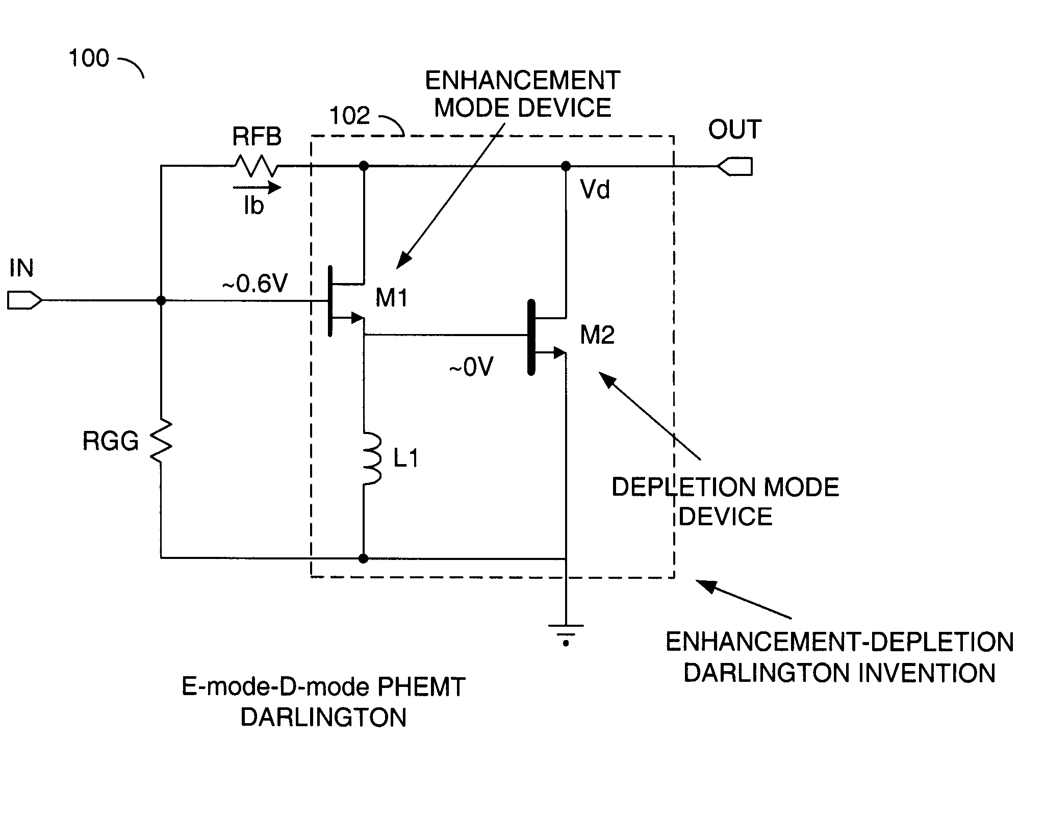
[0026]The present invention uses a combination of enhancement-mode and depletion-mode devices to construct a Darlington which is not voltage swing limited as in the conventional Darlington implementations.

[0027]Referring to FIG. 4, a system 30 illustrating an E-mode PHEMT Darlington amplifier is shown. The system 30 shows an implementation for reducing knee voltage in a Darlington feedback amplifier. The system 30 uses low threshold voltage E-mode PHEMTs to construct a Darlington. Since the turn-on voltage of the PHEMTs are ˜0.6V, the knee voltage will be reduced by ˜0.7 compared to a GaAs HBT Darlington and a few tenths of a volt reduction compared to a SiGe HBT implementation. The E-mode PHEMT implementation offers other advantages over GaAs / InGaP and SiGe HBT implementations such as lower noise, lower parasitics, and higher linearity (IP3) bandwidth.

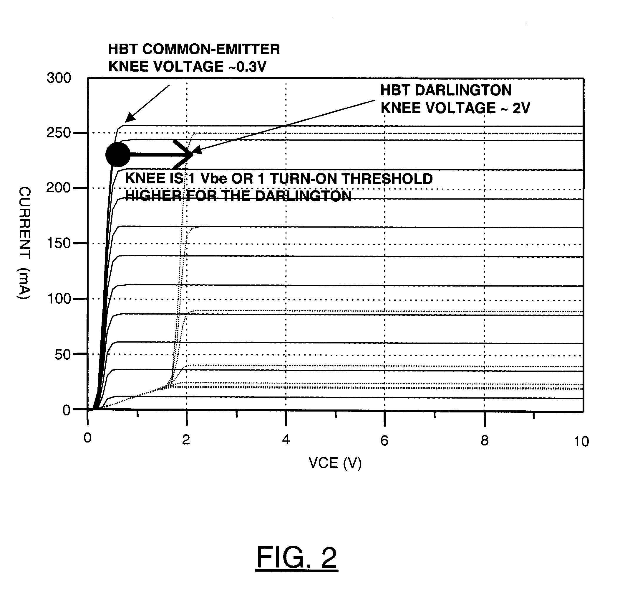
[0028]Referring to FIG. 5, a diagram illustrating the I-V characteristics of the system 30 compared to a GaAs HBT Darlington is show...


PUM


Abstract

An apparatus comprising a Darlington transistor pair comprising a first transistor and a second transistor. The first transistor may have a gate configured to receive an input signal. The second transistor may have a gate coupled to a source of the first transistor. The Darlington transistor pair may be configured to generate an output signal at a drain of the first transistor and a drain of the second transistor in response to the input signal. The first transistor may be implemented as an enhancement mode device and the second transistor may be implemented as a depletion mode device.

Description


Claims


Application Information

Patent Timeline
Owner QORVO US INC
Why Eureka
Try Eureka