Microwave detection system and method

a detection system and microwave technology, applied in the field of microwave detection system, can solve the problems of false detection of obstacles, inaccurate detection of obstacles, and add to the complexity and cost of the system

Active Publication Date: 2008-10-21
PROGRESS RAIL SERVICES
View PDF27 Cites 14 Cited by
  • Summary
  • Abstract
  • Description
  • Claims
  • Application Information

AI Technical Summary

Problems solved by technology

However, in this known implementation, the system includes a receiver, circulator, transit time element, a directional separating filter, and an amplifier, each of which incrementally adds to the complexity and cost of the system.
However, prior art systems currently encounter problems such as false detection of obstacles, inaccurate detection of obstacles, failure to detect obstacles, detection of echoes, inadequate surveillance, and high cost associated with the initial installation and with ongoing operations.

Method used


Image

  • Microwave detection system and method
  • Microwave detection system and method
  • Microwave detection system and method

Examples


Embodiment Construction

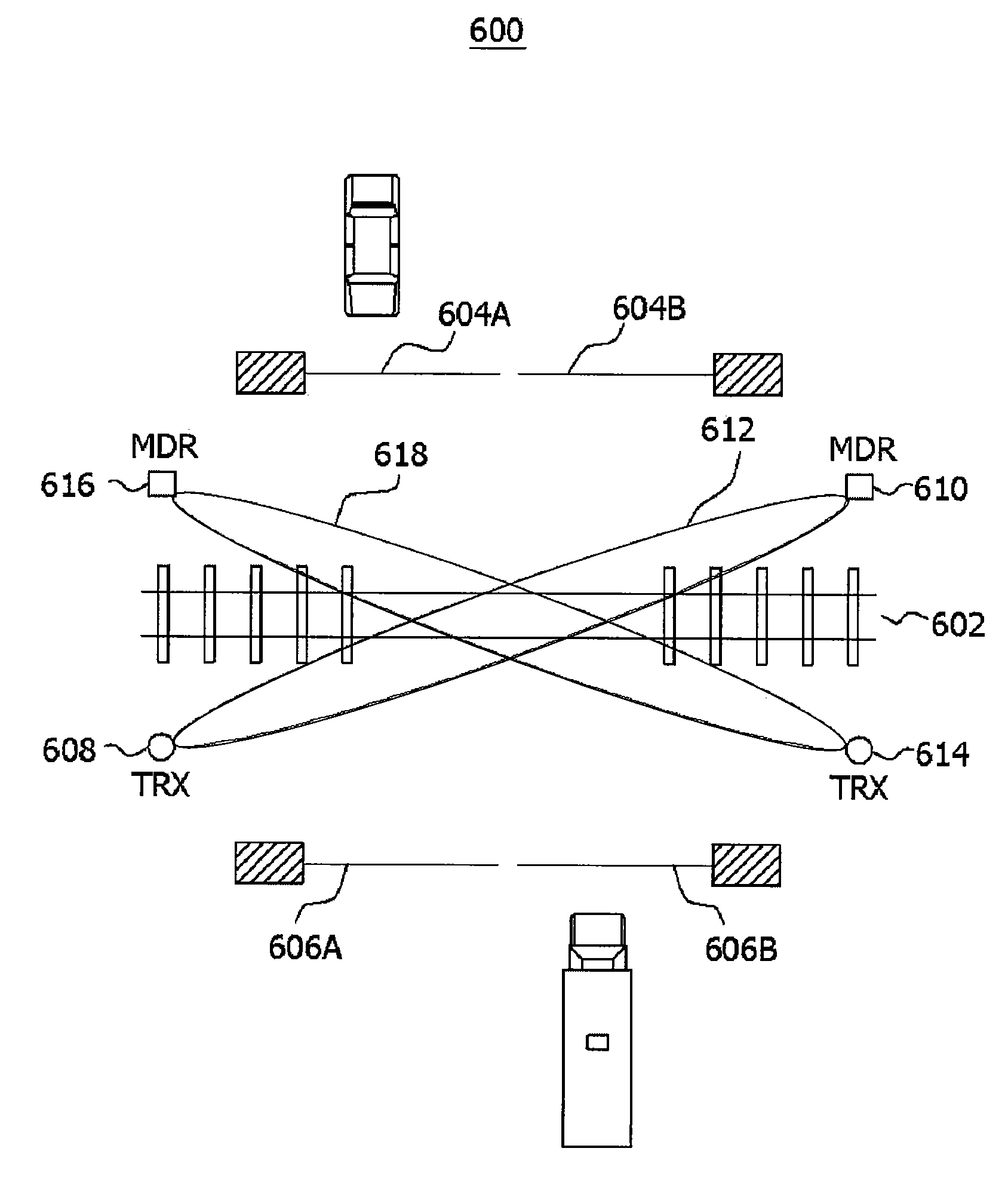
[0023]Aspects of the present invention are directed to a microwave detection system, such as may be used for automatically detecting intrusion to an off-limits zone using a modulated microwave signal. The description below will first describe one embodiment such as may be used for automatically detecting the presence of obstacles within the zone of a railroad track grade crossing. The description will then describe another embodiment such as may be used for automatically detecting intrusion through one or more perimeters that define an off-limits zone, such as may used at an airport.

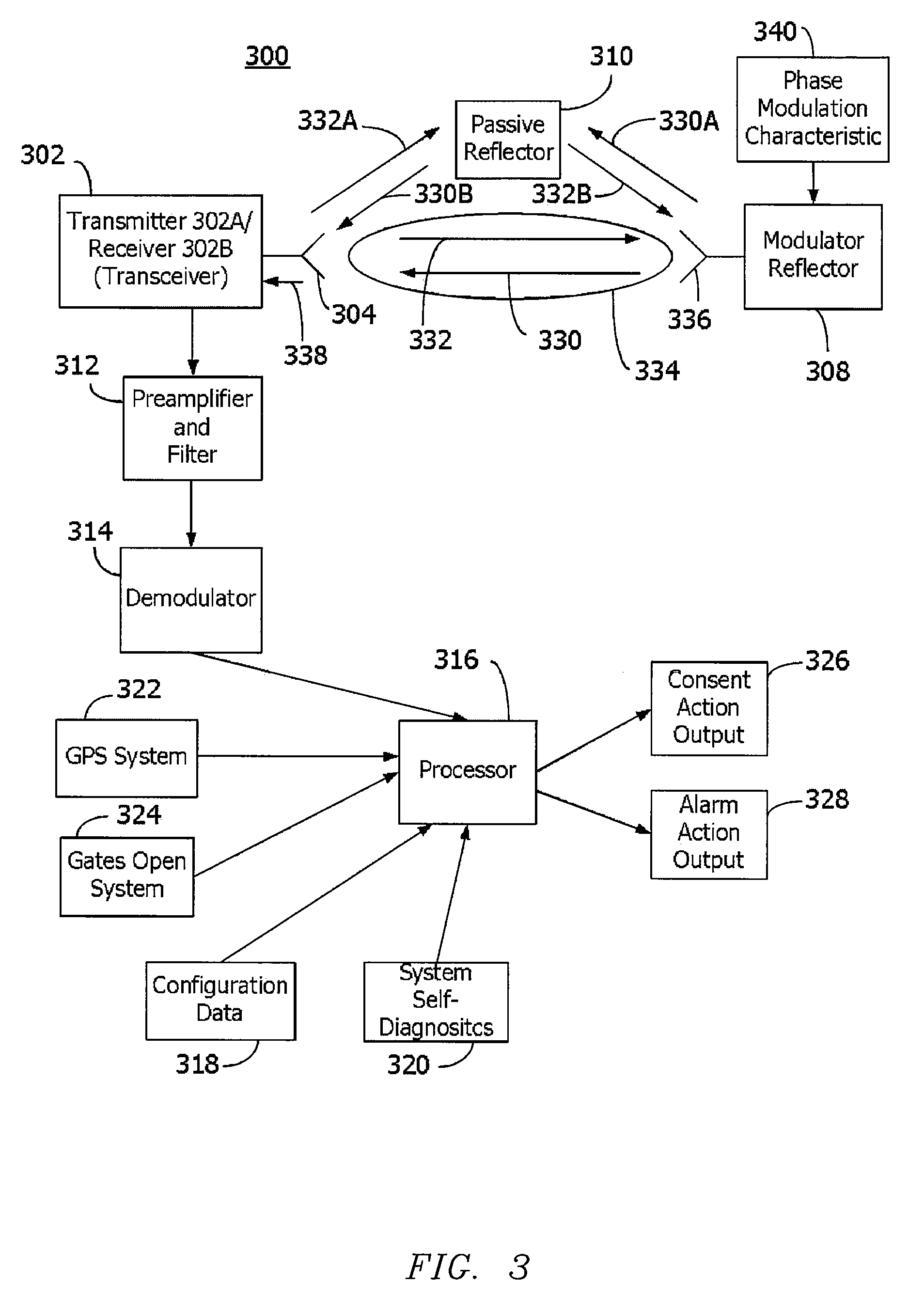
[0024]FIG. 3 is a simplified block diagram of one embodiment of a system 300 for automatically detecting intrusion in an off-limits zone, such as detecting the presence of an obstacle within the zone of a railroad track grade crossing using a microwave transmitter / receiver 302 and a modulating reflector 308. Transmitter / receiver 302 is equipped with an antenna 304. As shown, transmitter / receiver 302 may ...


PUM


Abstract

A microwave detection system includes a transmitter configured to transmit a signal along a path to detect an intruder to a monitored zone and a modulating reflector configured to receive the transmitted signal to generate a modulated signal having a characteristic introduced by said modulating reflector, the modulating reflector being configured to transmit the modulated signal. The system also includes a receiver located to receive the modulated signal and an adaptive threshold adjustment unit configured for providing a variable detection threshold responsive to a change in a gain of the system. The system further includes a processor configured for processing the modulated signal provided by the receiver and configured for measuring a characteristic in the processed modulated signal with respect to the variable detection threshold provided by the adaptive threshold adjustment unit.

Description

SPECIFIC DATA RELATED TO THE INVENTION[0001]This is a continuation-in-part of U.S. non-provisional patent application Ser. No. 11 / 195,145, filed Aug. 2, 2005 now U.S. Pat. No. 7,295,111, which in turn claims priority from U.S. non-provisional patent application Ser. No. 10 / 647,413, filed Aug. 25, 2003, now issued as U.S. Pat. No. 6,933,858, which in turn claims priority from U.S. provisional patent application No. 60 / 405,490, filed Aug. 23, 2002, each of which is incorporated by reference herein in its entirety.[0002]This application also claims the benefit of U.S. provisional application Ser. No. 60 / 753,907, filed Dec. 23, 2005, which is incorporated by reference herein in its entirety.FIELD OF THE INVENTION[0003]The invention relates generally to a microwave detection system. More particularly, the invention relates to a system and method for automatically detecting intrusion in an off-limits zone.BACKGROUND OF THE INVENTION[0004]FIG. 1 illustrates a typical prior art railroad gra...

Claims


Application Information

Patent Timeline
Patent Type & Authority Patents(United States)
IPC IPC(8): G08G1/16
CPCG01S13/04G01S13/756G08B13/2491G08B13/2494B61L29/30G01S7/4008G01S7/4021
Inventor PIERALLI, MORENOTORASSA, PAOLOZADEH, MASOUD M.
Owner PROGRESS RAIL SERVICES
Why Eureka
Try Eureka