
16 bit quadrature direct digital frequency synthesizer using interpolative angle rotation

a direct digital frequency and quadrature technology, applied in the field of direct digital frequency synthesis methods and apparatuses, can solve the problems of lack of tuning flexibility and neither option supports high-speed output frequency hopping

Active Publication Date: 2008-10-21
QUALCOMM INC
View PDF6 Cites 41 Cited by
  • Summary
  • Abstract
  • Description
  • Claims
  • Application Information

AI Technical Summary

Benefits of technology

The invention provides a function generator that creates an output signal representing a trigonometric function in response to an input signal representing an angle. The function generator uses interpolation of known angles and complex arithmetic to calculate the function. The invention also includes a direct digital synthesizer that generates multiple output signals representing different trigonometric functions. The function generator and the direct digital synthesizer can be used in various applications such as communication systems and radar systems.

Problems solved by technology

While the analog output fidelity, jitter, and AC performance of this simplistic architecture can be quite good, it lacks tuning flexibility.
Neither of these options support high-speed output frequency hopping such as used in spread spectrum modulation techniques of wireless radio frequency transmission.

Method used


Image

  • 16 bit quadrature direct digital frequency synthesizer using interpolative angle rotation
  • 16 bit quadrature direct digital frequency synthesizer using interpolative angle rotation
  • 16 bit quadrature direct digital frequency synthesizer using interpolative angle rotation

Examples


Embodiment Construction

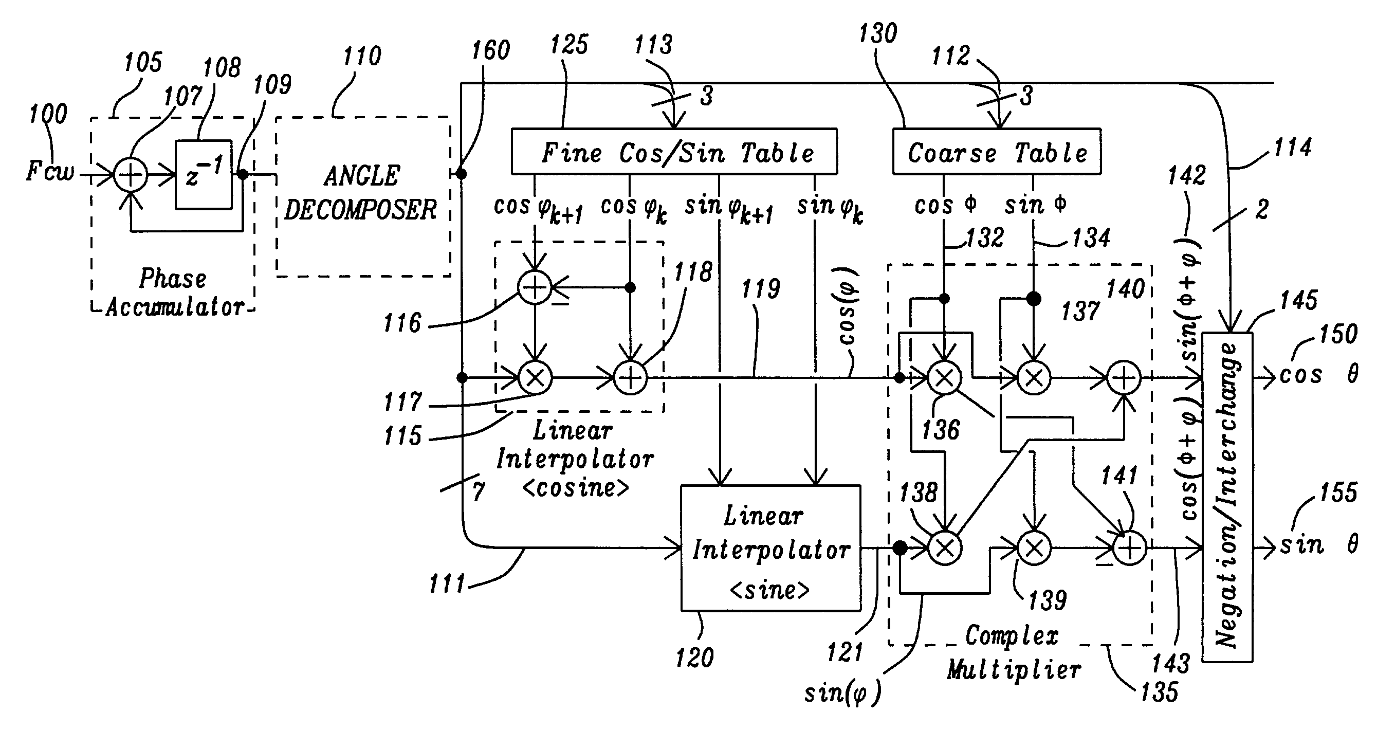
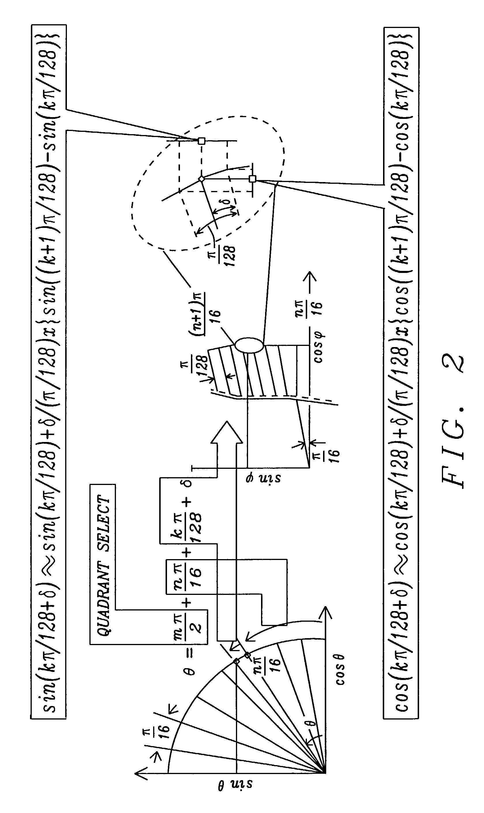
[0039]The direct digital frequency synthesizer of this invention has a trigonometric function generator that upon receipt of an input signal representing a phase angle provides an output signal representing at least one trigonometric function of the phase angle. The trigonometric function generator decomposes the phase angle into multiple sub-angles. One of the sub-angles indicating the quadrant of the unit circuit 50 of FIG. 1c. A second sub-angle is a coarse increment of a quadrant of the unit circuit 50 and a third sub-angle is a fine increment of the coarse increment. The phase angle is the sum of the sub-angles and a small differential between two of the third fine increments.

[0040]The trigonometric function generator determines the trigonometric function of the sub-angle of the coarse increment and then interpolates the trigonometric function between the trigonometric function of each of the two of the fine increments larger and smaller than smallest sub-angle of the decompose...


PUM


Abstract

A direct digital synthesizer employs a trigonometric function generator utilizing decomposition of a larger angle into smaller sub-angles, interpolation of a desired sub-angle between two known angles and calculating the trigonometric function using complex arithmetic. The direct digital synthesizer has a phase accumulator to generate an angular increment signal of the output signal. A trigonometric function generator in communication with the phase accumulator receives the angle signal and from the angle signal creates the trigonometric function signal. An angle decomposing circuit is connected to receive the angle signal to separate the angle signal into sub-angles of the angular increment, a sum of the sub-angles equaling the angular increment. An interpolation circuit receives the smallest of the sub-angles to generate the trigonometric function for the smallest of the sub-angles by interpolating between the trigonometric function of two known angles. The direct digital synthesizer has a first angle trigonometric retaining for retaining the trigonometric functions of the known angles. At least one second angle trigonometric retaining circuit retains the trigonometric functions of for the remaining sub-angles. A complex arithmetic unit combines the interpolated trigonometric function and the second trigonometric function from each of the second angle trigonometric retaining circuits to create the trigonometric function.

Description

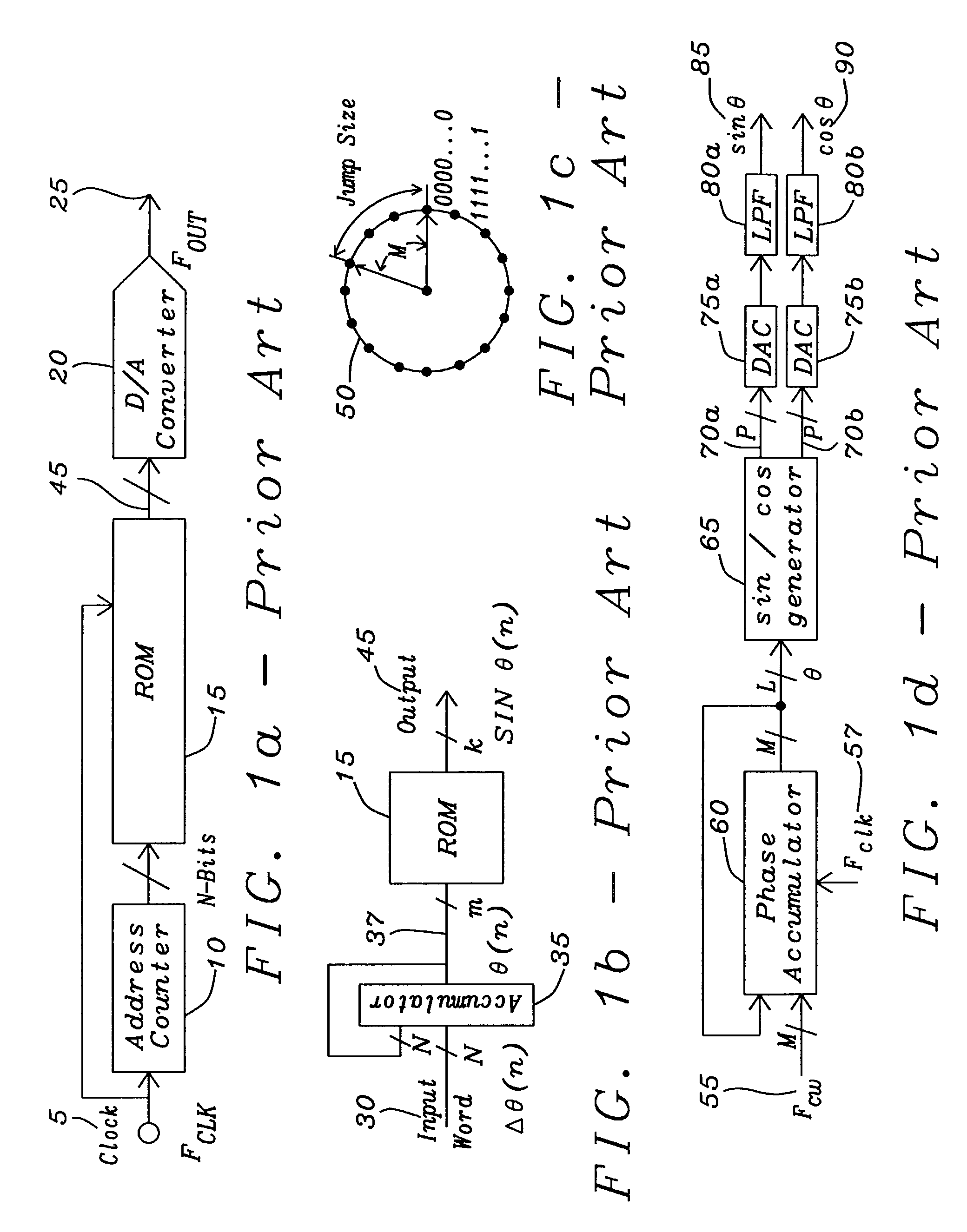
BACKGROUND OF THE INVENTION[0001]1. Field of the Invention[0002]This invention relates to methods and apparatus for direct digital frequency synthesis. More particularly this invention relates to methods and apparatus for direct digital frequency synthesis employing interpolation of trigonometric functions of angles between the trigonometric function of known angles.[0003]2. Description of Related Art[0004]As is described in A Technical Tutorial on Digital Signal Synthesis, Analog Devices, Norwood, Mass., 199, pp. 5-9, and shown in FIG. 1a, a direct digital synthesizer in its simplest form is implemented from a precision reference clock 5, an address counter 10, a read only memory (ROM) 15, and a digital-to-converter 20. The digital amplitude information that corresponds to a complete cycle of a sine wave is stored in the ROM 15 as a table of sine functions with the addresses of the ROM 15 acting as the angular values of the sine contents of the table. The address counter 10 steps t...

Claims


Application Information

Patent Timeline
Patent Type & Authority Patents(United States)
IPC IPC(8): G06F1/02
CPCG06F1/0353G06F1/0356
Inventor SONG, YONGCHULKIM, BEOMSUP
Owner QUALCOMM INC
Learn More