
Ground anchor load testing system and method

Inactive Publication Date: 2008-10-28
DAVIS JOHN D
View PDF18 Cites 12 Cited by
  • Summary
  • Abstract
  • Description
  • Claims
  • Application Information

AI Technical Summary

Benefits of technology

[0005]The ground anchoring unit may include a separate ground anchor and an extension at least axially push rigidly and rotationally rigidly combinable via an anchor coupling. In that case, the extension may provide the bare upper shaft portion. The anchor coupling may have an outer coupling diameter that is at least equal to the diameter of the reaction anchor's hollow shaft. During drill installation of the ground anchor and extension, the anchor coupling may thus radially widen the ground away from the bare upper portion. As a result, the hollow shaft may slide over the bare upper portion substantially unimpeded by the ground while the reaction anchor is drilled into the ground.
[0006]The concentric temporary installation of the single reaction anchor provides for a direct coupling of the test loading head with the reaction anchor and the ground anchoring unit under test. The bare upper shaft portion extending out of the ground serves favorably as a centering aid for easy positioning of the reaction anchor prior to drill installation. The load testing procedure is easy and fast to perform without any additional equipment. Optionally, the reaction anchor may be simultaneously drilled into the ground together with the ground anchoring unit.

Problems solved by technology

As a result, the hollow shaft may slide over the bare upper portion substantially unimpeded by the ground while the reaction anchor is drilled into the ground.

Method used


Image

  • Ground anchor load testing system and method
  • Ground anchor load testing system and method
  • Ground anchor load testing system and method

Examples


Embodiment Construction

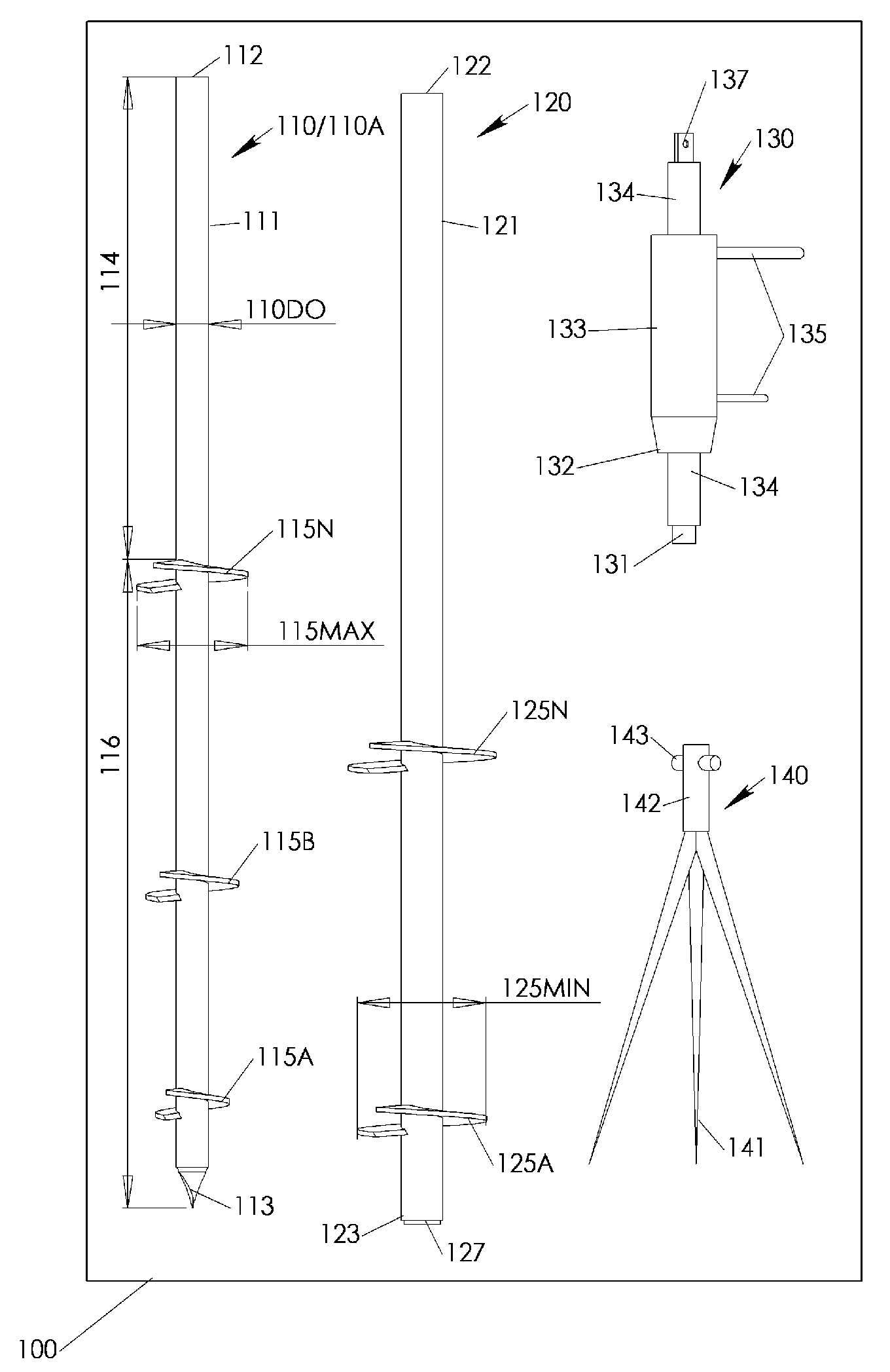
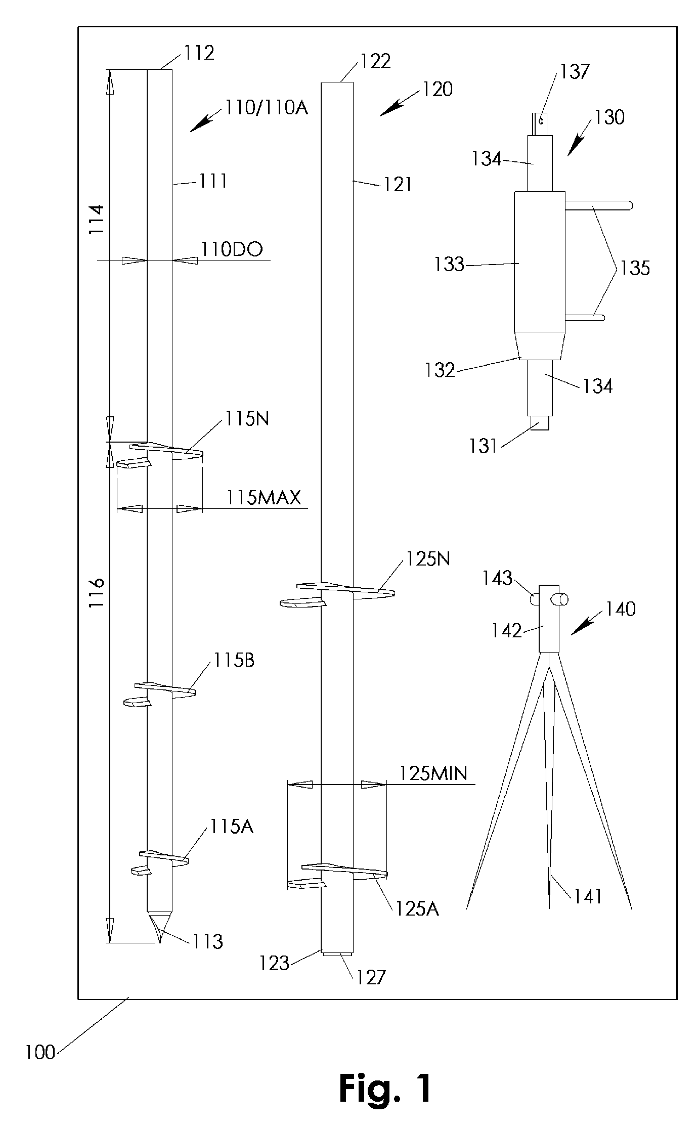
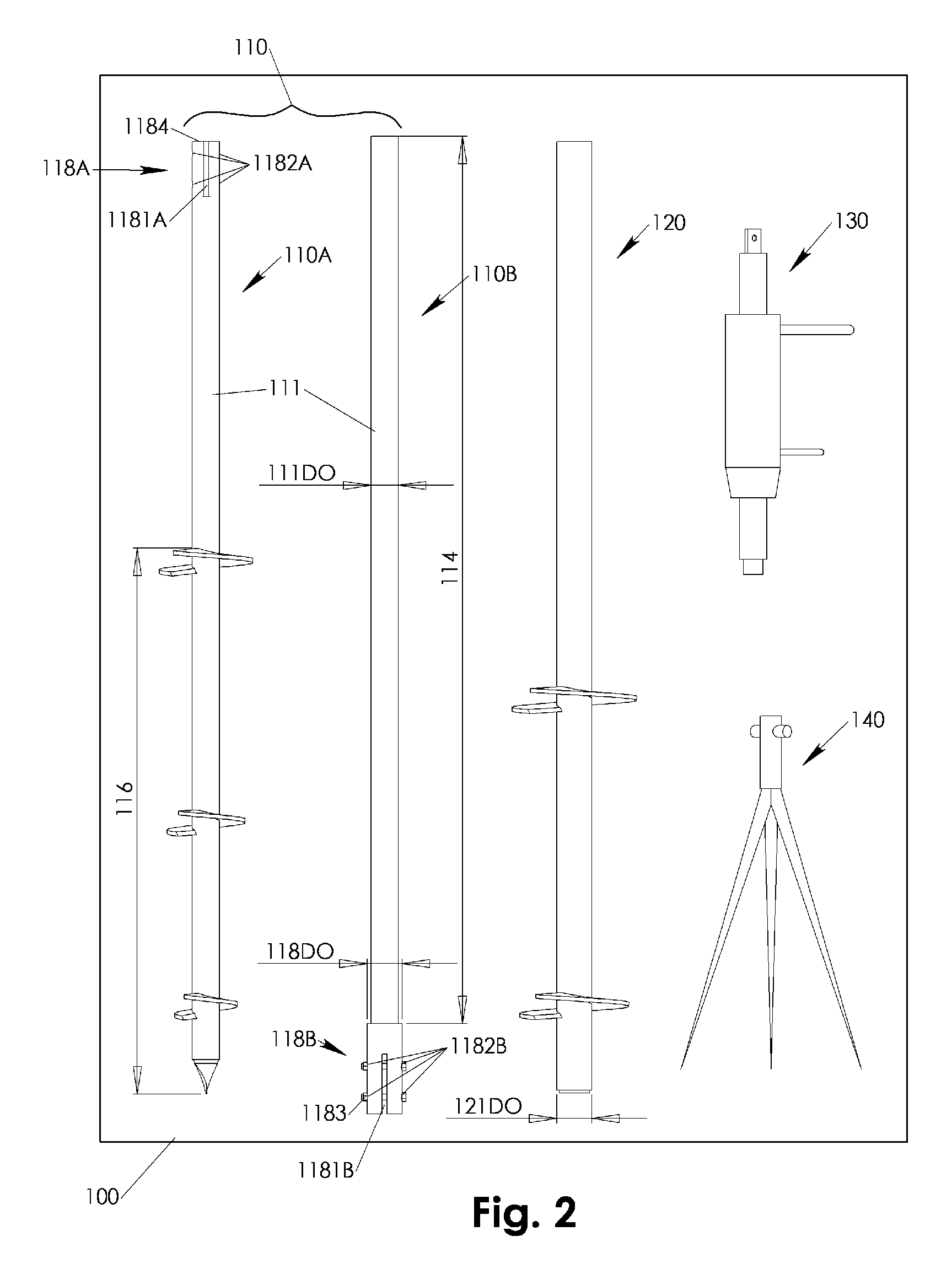
[0013]Referring to FIGS. 1-3, a ground anchor load testing system 100 may include a ground anchoring unit 110, a reaction anchor 120, a test loading head 130 and a ground referencing axial displacement measurement device 140. The ground anchoring unit 110 preferably includes a ground anchor 110A and an optional extension 110B. A drilling shaft 111 of the ground anchoring unit 110 has a drilling end 113, a first flanging end 112, a bare upper portion 114 adjacent the first flanging end 112 and a bottom portion 116 adjacent the drilling end 113. The bottom portion 116 features one or more push load ground transferring anchoring structure(s) 115A-N in the preferred configuration of helical plate(s). The primary helical plate(s) 115A-N may have a primary maximum diameter 115MAX, which in case of multiple helical plates 115A-N may be the diameter of the helical plate 115N furthest away from the drilling end 113.

[0014]In case of an additionally employed extension 110B, the ground anchor 1...


PUM


Abstract

A ground anchor load testing system includes a ground anchoring unit having a bare upper drill shaft portion along and around which a reaction anchor with its hollow shaft is temporary installed. During test loading of the installed ground anchoring unit, a test loading head is coupled with both concentric flanging ends of the ground anchoring unit and the temporarily installed reaction anchor. The test loading head exerts via a first coupling the push test load on the first flanging end of the ground anchoring unit while withholding itself via a second coupling on the second flanging end of the reaction anchor. A measurement device may be positioned on the ground adjacent the test load head. Eventual axial displacement of the ground anchoring unit under test load may be externally recognized by the measurement device via an axial displacement indicator in axial connection with the first coupling.

Description

FIELD OF INVENTION[0001]The present invention relates to systems and methods for testing an installed ground anchor. In particular, the present invention relates to systems and methods for testing an installed ground anchor by use of a single reaction anchor temporary installed concentrically with respect to the ground anchor.BACKGROUND OF INVENTION[0002]Ground anchors are increasingly used for residential architectural constructions and other construction projects requiring low cost foundation stabilization. Ground anchors may provide for cost effective stabilization of foundations without requiring expensive excavations and deeply embedded foundations. A variety of prior art ground anchors are employed at the time of this invention, mostly in configurations including helical plates welded to square or round shafts. Such well known ground anchors are commonly installed by drilling them deep into the ground.[0003]A main limitation of utilizing such ground anchors on a larger scale m...

Claims


Application Information

Patent Timeline
IPC IPC(8): G01L5/04E02D5/74E21D20/00G01L1/26
CPCE02D7/22E02D33/00E21B7/005G01L5/0038E02D5/801
Inventor DAVIS, JOHN D.
Owner DAVIS JOHN D
Learn More