Wave energy converter utilizing internal reaction mass and spring

a technology of reaction mass and wave energy, which is applied in the direction of electric generator control, machines/engines, mechanical equipment, etc., can solve the problems of short wec buoy and adverse hydrodynamic performance, and achieve the effect of reducing spring displacement, increasing spring stiffness, and being easy to constru

Active Publication Date: 2008-10-28
OCEAN POWER TECHNOLOGIES
View PDF5 Cites 65 Cited by
  • Summary
  • Abstract
  • Description
  • Claims
  • Application Information

AI Technical Summary

Benefits of technology

[0011]Wave forces and viscous damping limit the extent to which the float and spar can move relative to each other, thereby decreasing the potential for energy collection.
[0022]In accordance with one embodiment of the invention, a physical spring is connected to the reaction mass by a “block and tackle” pulley system. In this system, the spring stiffness is increased by, and the spring displacement is decreased by, the multiplying ratio of the pulley system. It is much easier to construct a short, stiff spring than it is to construct a long, soft spring. It is also easier to fit such a spring inside a WEC buoy. Even if it were possible to construct a long spring with the proper force-displacement characteristic, the volume of the WEC buoy being occupied by the spring and reaction mass would cause the WEC buoy to be long and its hydrodynamic performance could be adversely impacted.
[0025]As further discussed below other embodiments have been devised by the Applicants to help keep the size and stiffness of the springs within a practical range.

Problems solved by technology

Even if it were possible to construct a long spring with the proper force-displacement characteristic, the volume of the WEC buoy being occupied by the spring and reaction mass would cause the WEC buoy to be long and its hydrodynamic performance could be adversely impacted.

Method used


Image

  • Wave energy converter utilizing internal reaction mass and spring
  • Wave energy converter utilizing internal reaction mass and spring
  • Wave energy converter utilizing internal reaction mass and spring

Examples


Embodiment Construction

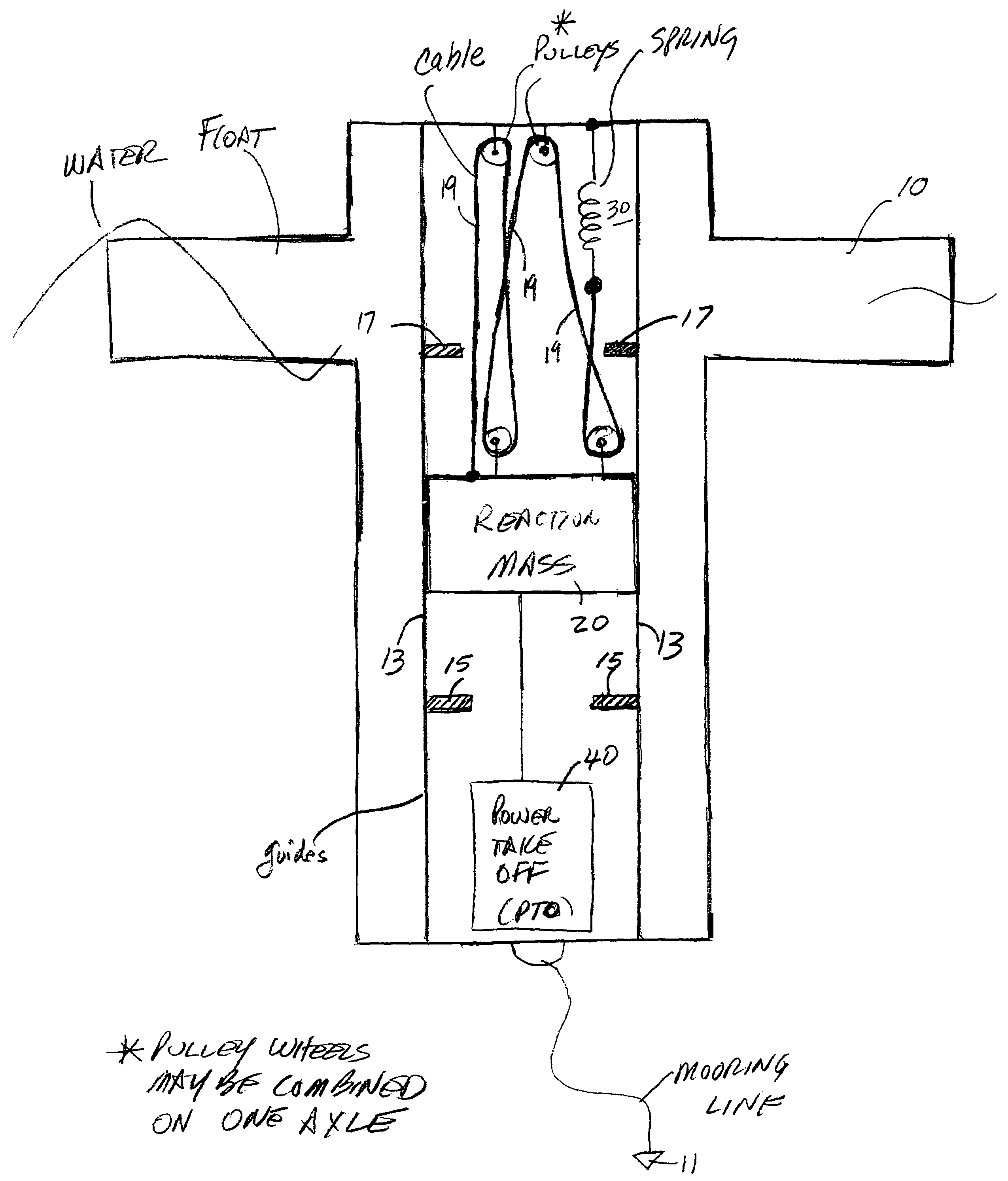
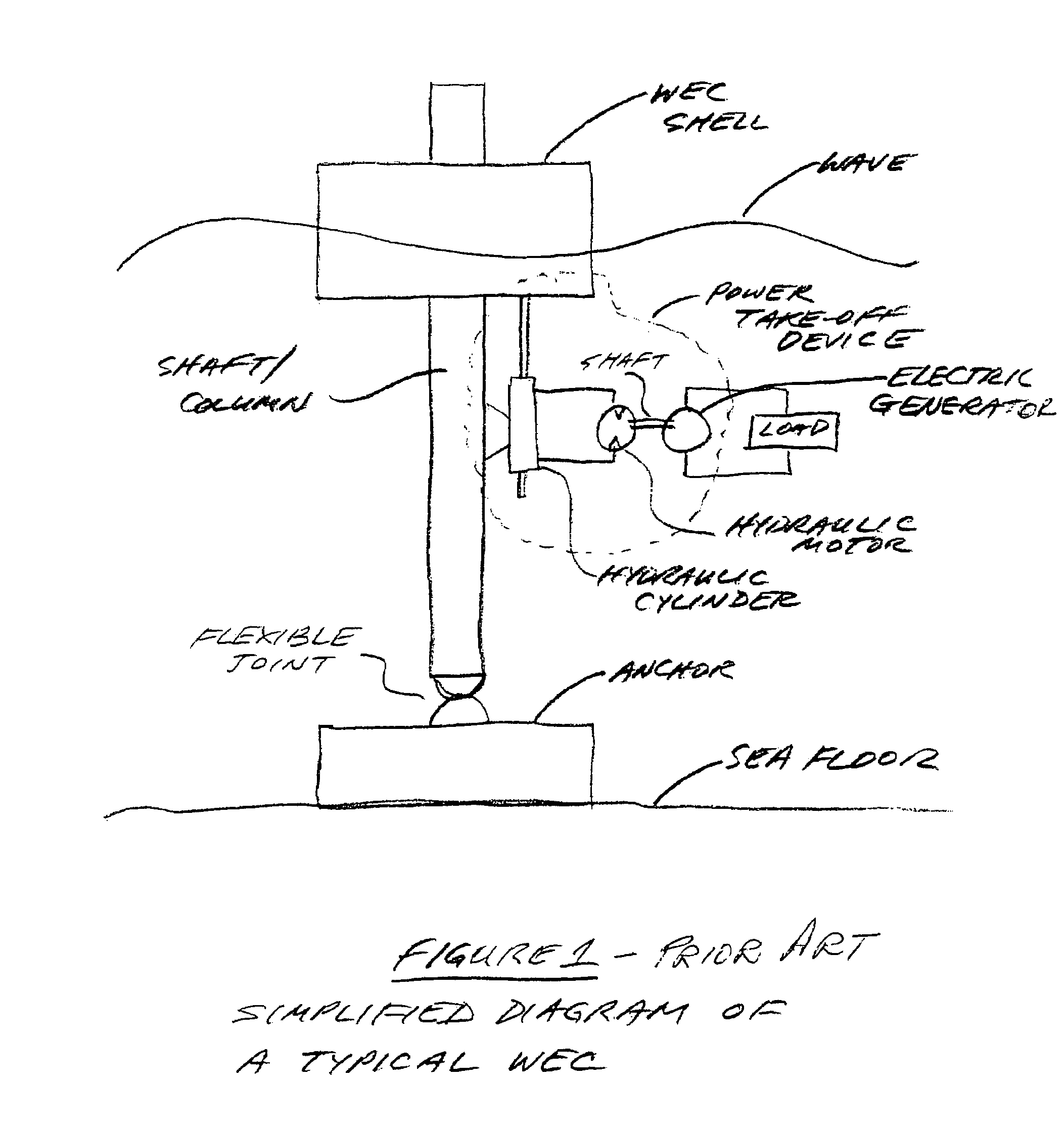
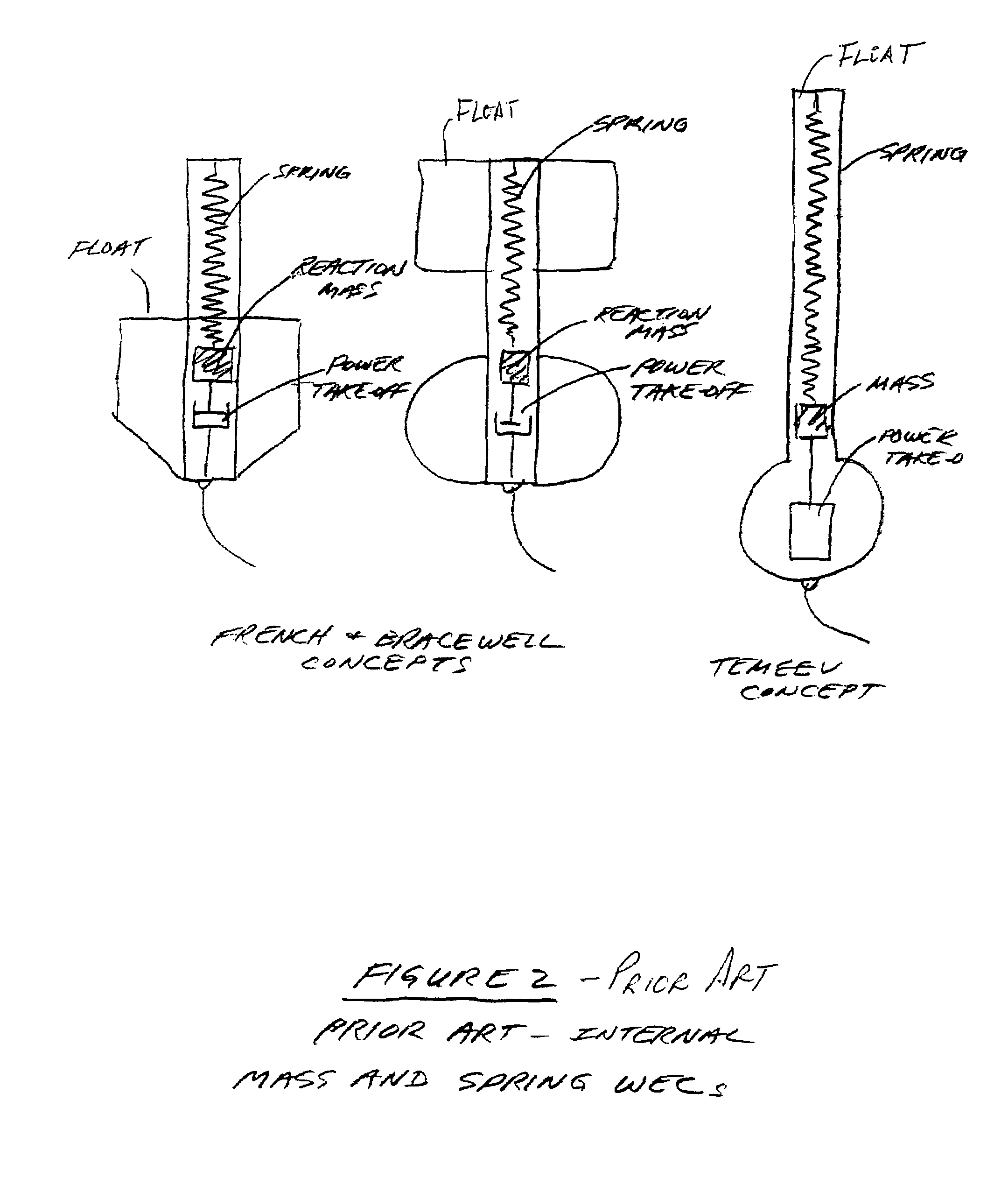
[0042]As discussed above with reference to FIGS. 1 and 2 and as noted in references (1) and (2), cited above, it has been suggested to overcome problems with existing WECs in which the spar, float and PTO device are exposed to the water by constructing a WEC with a “shell” (float) that is acted upon by the waves and using a “reaction” mass that is totally contained within the float with a spring and power take-off device that couple the reaction mass to the float. In this type of system, the enclosed mass (m) is suspended from or supported by a spring that is connected to the float and whose force constant (k) is tuned to give the desired natural period (Tn) of the WEC. A problem with this approach (i.e., selecting the spring force characteristic to yield a desired natural period) is that the required length of the spring is so long (large) that it is not practical to construct it or house it within the float. The length of the spring in still water (x0) can be determined by solving...


PUM


Abstract

A wave energy converter (WEC) includes a shell suitable for being placed within a body of water. The shell contains an internal oscillator comprising a “reaction mass” and a spring mechanism coupled between the reaction mass and the shell. The shell and internal oscillator are constructed such that, when placed in a body of water and in response to waves in the body of water, there is relative motion between the shell and the internal oscillator's mass. A power take-off (PTO) device is coupled between the internal oscillator and the shell to convert their relative motion into electric energy. In systems embodying the invention, the spring mechanism is designed such that its displacement or movement is less than the displacement or movement of the reaction mass. The spring mechanism may be any device which enables the reaction mass to undergo a given replacement while its displacement or movement is less than that of the reaction mass. This property enables the size of the WEC to be more readily controlled (e.g., made smaller).

Description

BACKGROUND OF THE INVENTION[0001]This application claims the benefit of Provisional Application No. 60 / 741,108 filed Dec. 1, 2005 and its teachings are incorporated herein by reference.[0002]This invention relates to apparatus for converting energy present in surface waves of large bodies of water into useful electrical energy.[0003]Various wave energy converter (WEC) systems are known. For example, reference is made to U.S. patent application Ser. No. 09 / 379,421 filed Aug. 21, 1999, titled “Wave Energy Converter Utilizing Pressure Difference”, assigned to the assignee of the present application and the teachings of which are incorporated herein by reference.[0004]Known WEC systems generally include a “float” (or “shell”) and a “spar” (or “shaft” or “column” or “piston”) which are designed to move relative to each other to convert the force of the waves into mechanical energy. In these systems, the float is generally depicted or referred to as the moving member and the spar as the n...

Claims


Application Information

Patent Timeline
Patent Type & Authority Patents(United States)
IPC IPC(8): F03B13/12
CPCF03B13/20Y02E10/38F05B2260/502Y02E10/30F05B2250/44
Inventor STEWART, DAVID B.GERBER, JAMES S.
Owner OCEAN POWER TECHNOLOGIES
Why Eureka
Try Eureka