
Data sharing system, transmitting terminal apparatus, transmitting terminal apparatus controlling method, receiving terminal apparatus, receiving terminal apparatus controlling method, and recording medium

a data sharing and terminal technology, applied in data switching networks, frequency-distribution multiplexes, instruments, etc., can solve the problems of inefficient and wasteful interlocking process between the transmitting and the receiving terminal apparatus, large loss of time in transmitting data, and faulty interlocking process, so as to avoid wasteful attempts at starting the function and improve the user's work efficiency

Inactive Publication Date: 2008-10-28
SONY CORP
View PDF18 Cites 8 Cited by
  • Summary
  • Abstract
  • Description
  • Claims
  • Application Information

AI Technical Summary

Benefits of technology

[0011]The communication performance measuring means measures at predetermined time intervals the communication performance parameters representative of network communication performance between the transmitting terminal apparatus and the receiving terminal apparatus. The communication performance parameters are constituted illustratively by a delay time and a packet loss rate. The transmitting terminal apparatus is thus capable of collecting data such as the transfer rate and communication performance parameters representative of network communication status. The evaluating means of the apparatus calculates the evaluation parameters of the ongoing network communication status using a plurality of data items made up of the collected transfer rate and communication performance parameters. The calculated evaluation parameters make it possible to monitor the current network communication status with ease.
[0029]Where the transmitting terminal apparatus controlling method above is used in conjunction with the data sharing system including the transmitting and receiving terminal apparatuses, the transmitting terminal apparatus is arranged to set an optimum transfer rate reflecting the current network communication status for efficient data transfer. By collecting data from time to time about how communication is taking place over the network and by calculating the evaluation parameters accordingly, the transmitting terminal apparatus under control of the inventive method can readily recognize the network communication status and regulate the interlocking process with regard to the receiving terminal apparatus in keeping with the recognized communication status. For example, the inventive method allows the transmitting terminal apparatus to take action immediately if the status becomes such as to exclude effectively the feasibility of real-time-oriented processing between the transmitting terminal apparatus and the receiving terminal apparatus. The action thus taken helps the user to avert wasteful attempts at starting the currently unavailable process, whereby the user's work efficiency is improved.

Problems solved by technology

That can result in a huge loss of time in transmitting data.
That is inefficient and wasteful.
In another example, if there occur delays or losses in data transfers, the interlocking process between the transmitting and the receiving terminal apparatuses may well end up faulty.
Conventionally, however, these functions are left apparently operable even though they are not.
This can result in a significant decline in the user's work efficiency.

Method used


Image

  • Data sharing system, transmitting terminal apparatus, transmitting terminal apparatus controlling method, receiving terminal apparatus, receiving terminal apparatus controlling method, and recording medium
  • Data sharing system, transmitting terminal apparatus, transmitting terminal apparatus controlling method, receiving terminal apparatus, receiving terminal apparatus controlling method, and recording medium
  • Data sharing system, transmitting terminal apparatus, transmitting terminal apparatus controlling method, receiving terminal apparatus, receiving terminal apparatus controlling method, and recording medium

Examples


Embodiment Construction

[0051]Preferred embodiments of this invention will now be described in detail with reference to the accompanying drawings. In the drawings and in the description that follows, like reference characters designate like or functionally corresponding parts, and their descriptions will be omitted where redundant.

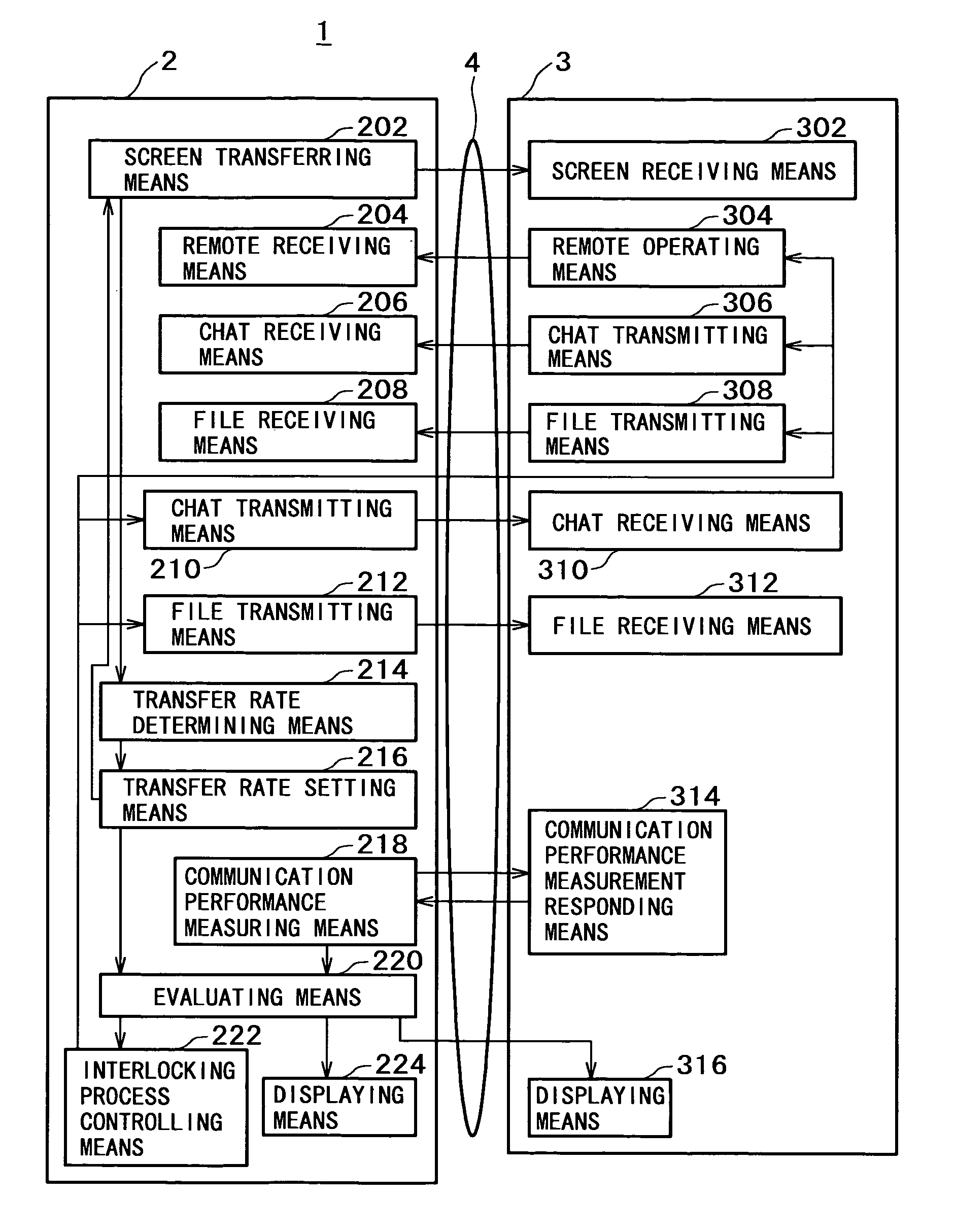
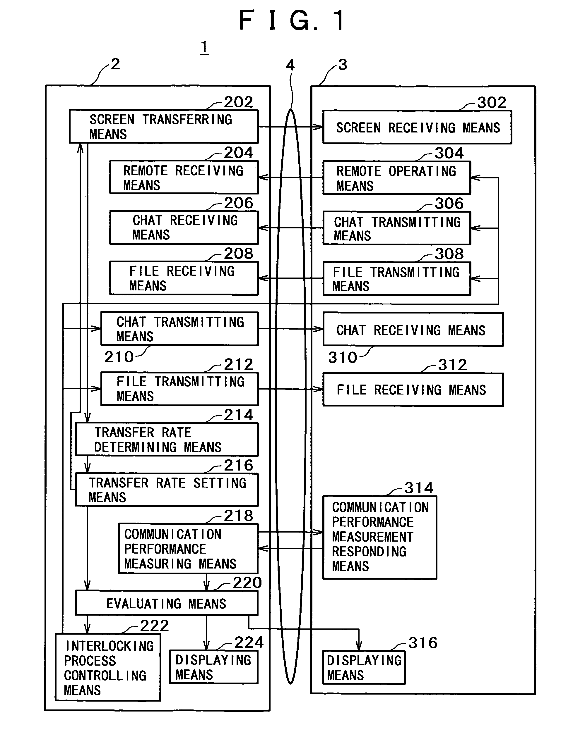
[0052]A typical configuration of a data sharing system embodying the invention is explained below with reference to FIG. 1. FIG. 1 is a block diagram showing how the data sharing system 1 of the invention is configured. The data sharing system 1 is constituted primarily by a transmitting terminal apparatus 2, a receiving terminal apparatus 3, and a network 4 connecting the transmitting and receiving terminal apparatuses 2 and 3. Although this embodiment is shown formed by one transmitting terminal apparatus 2 and one receiving terminal apparatus 3, this is not limitative of the invention.

[0053]In the data sharing system 1, part or all of display screen data (picture data) are sen...


PUM


Abstract

A data sharing system is disclosed together with a transmitting terminal apparatus and a receiving terminal apparatus interconnected and controlled so as to effect efficient data transfers and concomitant interlocking processes therebetween in keeping with network communication status. The transmitting terminal apparatus illustratively includes a transfer rate setting block for setting a transfer rate based on how fast display screen data were transferred previously to the receiving terminal apparatus, a communication performance measuring block for measuring communication performance parameters representative of network communication performance between the transmitting terminal apparatus and the receiving terminal apparatus, an evaluating block for calculating evaluation parameters for evaluating the network communication status using at least the transfer rate and the communication performance parameters, and an interlocking process controlling block for controlling an interlocking process between the transmitting terminal apparatus and the receiving terminal apparatus by use of the evaluation parameters.

Description

BACKGROUND OF THE INVENTION[0001]The present invention relates to a data sharing system for sharing display screen data between a plurality of terminal apparatuses, as well as to a transmitting terminal apparatus, a transmitting terminal apparatus controlling method, a receiving terminal apparatus, a receiving terminal apparatus controlling method, and a recording medium which stores programs, all for use by the system.[0002]There exist systems today each designed to transfer data between a plurality of terminal apparatuses connected via a network so that the data may be shared between the connected apparatuses. One such system is a display screen sharing system that has display screen data shared by a plurality of terminals connected via a network illustratively for networked conference purposes. In a conference based on the system, a presenter's terminal apparatus (i.e., transmitting terminal apparatus) transmits display screen data that are received by other participants' termina...

Claims


Application Information

Patent Timeline
IPC IPC(8): H04J3/16G06F13/00H04L29/08
CPCH04L47/10H04L47/11
Inventor OHKI, KAZUHIROAZUMA, TAKAFUMI
Owner SONY CORP
Learn More