Positional marker system with point light sources

a technology of point light source and marker, which is applied in the field of positioning marker system, can solve the problems of large space occupation of markers, difficult to attach to small or very thin objects, and large dimensions of markers and/or the active or emitting portion of markers

Inactive Publication Date: 2008-10-28
BRAINLAB
View PDF46 Cites 63 Cited by
  • Summary
  • Abstract
  • Description
  • Claims
  • Application Information

AI Technical Summary

Problems solved by technology

A disadvantage of previously known, active markers such as, for example, LED markers, is the relatively large dimensions of the markers and / or the active or emitting portion of the markers.
More specifically, the markers take up a relatively large space and are difficult to attach to smaller or very thin objects.
Also, LEDs provide a very non-homogeneous light pattern.
As for the passive markers, the problem arises that they have to be relatively large in order to be detected by the cameras.
Relatively large markers, however, can become partially covered or tarnished while being used, or, due to manufacturing tolerances, can exhibit a shape which is not entirely regular.
If the markers are partially covered, tarnished or of different sizes, however, it may not be possible to precisely calculate the center point.
Errors arise, which, in applications that demand a high degree of accuracy (e.g., surgical applications) are undesirable.

Method used


Image

  • Positional marker system with point light sources
  • Positional marker system with point light sources
  • Positional marker system with point light sources

Examples


Embodiment Construction

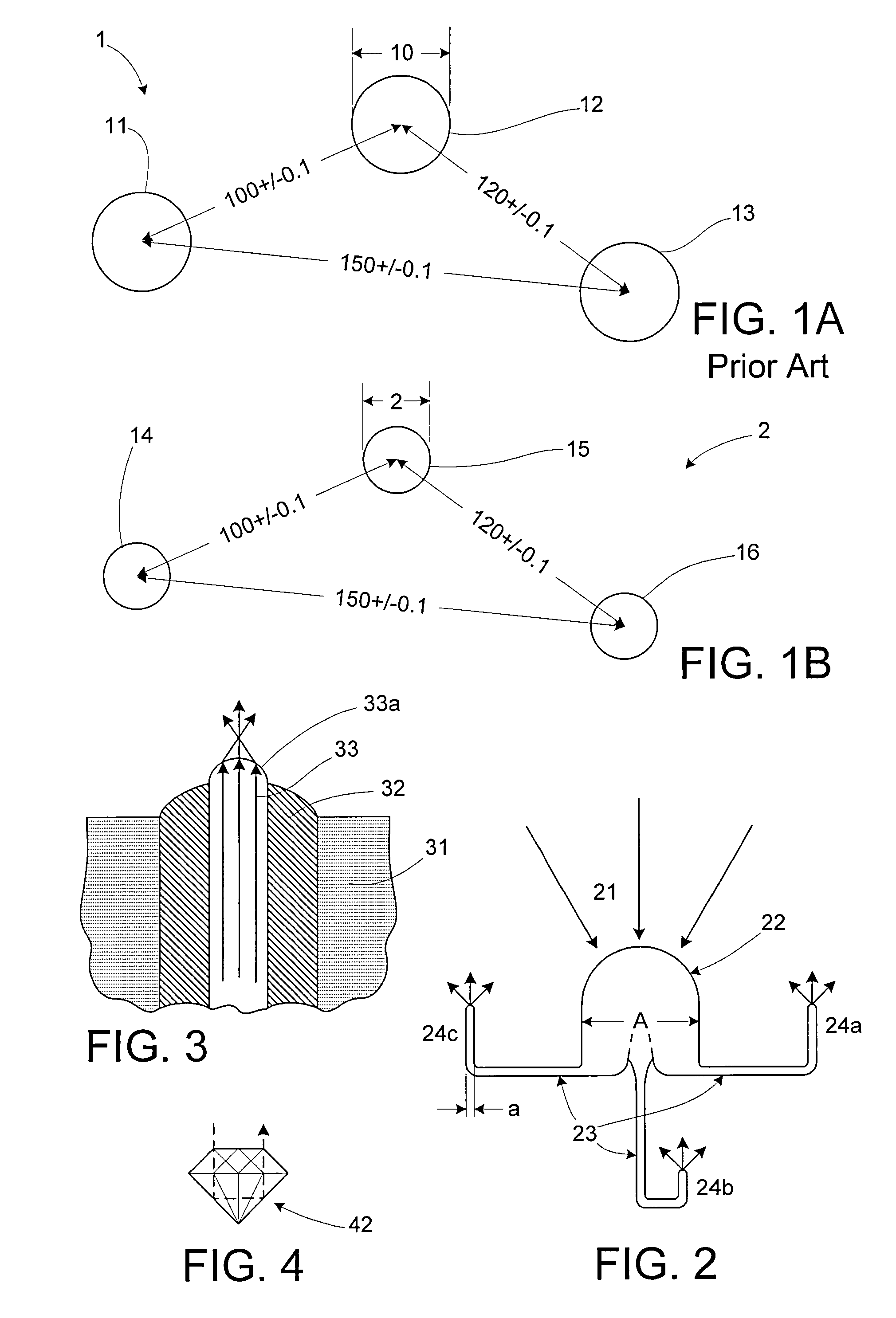
[0024]FIGS. 1A and 1B show a contrast between a conventional positional marker system 1 (FIG. 1A) and a positional marker system 2 (FIG. 1B) in accordance with the invention. The markers of the conventional system 1 are the actual reflecting surface of a reflector marker 11, 12, 13. Usually, spherical or discoid retro-reflecting surfaces are used that reflect light in an output direction over a relatively large area. This generates a projection of the marker within the tracking system. Three such markers, for example, can be attached to a patient's body part or on a rigid body (marker geometry), in order to ascertain a spatial position of the markers via a tracking system. The markers 11, 12 and 13 of the conventional marker system 1 exhibit different center-to-center distances from each other, such as, for example, 100, 120 and 150 mm, and they have a diameter of 10 mm. The positioning tolerance or positioning accuracy, e.g., the accuracy in determining the spatial position of indi...


PUM


Abstract

A positional marker system is disclosed. The positional marker system includes at least one light-emitting or light-reflecting marker that can be positionally detected by an optical tracking system, such as a medical tracking system, wherein the emitting and / or reflecting portion of the marker or markers is formed as a point light source and / or point light reflector.

Description

RELATED APPLICATION DATA[0001]This application claims priority of U.S. Provisional Application No. 60 / 619,352 filed on Oct. 14, 2004, which is incorporated herein by reference in its entirety.FIELD OF THE INVENTION[0002]The invention relates to a positional marker system and, more particularly, to a positional marker system that includes at least one light-emitting or light-reflecting marker that can be positionally detected by an optical tracking system.BACKGROUND OF THE INVENTION[0003]Positional marker systems for optical tracking systems and, in particular, medical tracking systems, are known in principle. For example, a reflector or reflective referencing system is known from DE 19 639 615 C2 (U.S. Pat. No. 6,351,659 B1), wherein the positional markers are formed as passive markers and include spheres with a reflective covering or coating. Optical radiation reflected off of these spheres can be detected by a camera-assisted tracking system, and their spatial position can be dete...

Claims


Application Information

Patent Timeline
Patent Type & Authority Patents(United States)
IPC IPC(8): A61B8/12A61N5/00G06T7/20
CPCA61B19/54G01S5/16G02B6/0008A61B2019/5287A61B2019/5437A61B2019/5445A61B2019/5479A61B2019/5483A61B90/39A61B2090/363A61B2090/3937A61B2090/3945A61B2090/3979A61B2090/3983
Inventor GOLDBACH, GUNTER
Owner BRAINLAB
Why Eureka
Try Eureka