Damascene process for fabricating poles in recording heads

Active Publication Date: 2008-11-04
WESTERN DIGITAL TECH INC
View PDF16 Cites 198 Cited by
  • Summary
  • Abstract
  • Description
  • Claims
  • Application Information

AI Technical Summary

Benefits of technology

[0009]FIG. 1 is diagram depicting a conventional perpendicular magnetic recording pole.
[0010]FIG. 2 is

Problems solved by technology

As a result, the height of the conventional pole 16 may be extremely difficult to control and fabrication of suitable conv

Method used


Image

  • Damascene process for fabricating poles in recording heads
  • Damascene process for fabricating poles in recording heads
  • Damascene process for fabricating poles in recording heads

Examples


Embodiment Construction

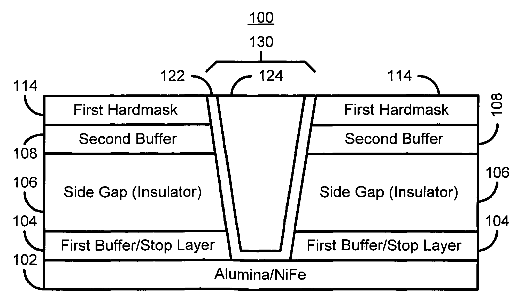
[0015]FIGS. 3A-3F depict a PMR head 100 formed in accordance with an exemplary embodiment of the present invention. To enhance clarity FIGS. 3A-3F are not drawn to scale. FIG. 3A depicts the layers of the PMR head 100 after initial deposition of the layers 102, 104, 106, and 108 surrounding the pole (not shown) and used in fabricating the PMR head 100. The layers includes an etch stop / buffer layer 104 on an underlying layer 102. The underlayer 102 preferably includes a bilayer of alumina on NiFe. The etch stop / buffer layer 104 preferably includes at least one of Ta, TaN, Ti, or TiN. The side gap layer 106 is preferably a low dielectric constant insulating material such as silicon nitride (SiNe), hydrogenated silicon nitride, silicon oxynitride (SiOxNy), hydrogenated silicon oxynitride, or silicon oxide (SiOx). Such low dielectric constant materials are preferred in order to facilitate processing described below. However, in an alternate embodiment, another insulating material, such ...


PUM


Abstract

A method and system for manufacturing a pole for a magnetic recording head. The method and system include providing an insulator and fabricating at least one hard mask on the insulator. The at least one hard mask has an aperture therein. The method and system also include removing a portion of the insulator to form a trench within the insulator. The trench is formed under the aperture. The method and system further include depositing at least one ferromagnetic material. The pole includes a portion of the ferromagnetic material within the trench.

Description

FIELD OF THE INVENTION[0001]The present invention relates to magnetic recording technology, and more particularly to a method and system for fabricating a perpendicular recording head.BACKGROUND OF THE INVENTION[0002]A conventional magnetic recording head includes a transducer deposited on a back surface of a slider. The slider also includes an air-bearing surface (ABS) that faces the recording media. FIG. 1 depicts a portion of conventional perpendicular magnetic recording (PMR) transducer 10 as viewed looking towards the ABS (not shown). The conventional PMR transducer 10 includes a conventional pole 16 and a top shield 24 separated by a write gap 20. Note that the top shield 24 also acts as pole during writing using the conventional PMR transducer 10. The conventional pole 16 and the top shield 24 are surrounded by insulating layers 18 and 22. The conventional pole 16 resides on a seed layer 12 and has sidewalls 14.[0003]In conventional applications, the height of the conventiona...

Claims


Application Information

Patent Timeline
IPC IPC(8): G11B5/127H04R31/00
CPCG11B5/3116G11B5/1278G11B5/3163Y10T29/49052Y10T29/49044Y10T29/49048Y10T29/49043Y10T29/49046
Inventor CHUNG, KI SUPSIN, KYUSIKYANG, DANNINGCHEN, YINGJIANNEASE, BRANT
Owner WESTERN DIGITAL TECH INC
Why Eureka
Try Eureka