
Sheller

a sheller and shell technology, applied in the field of improved shellers, can solve the problems of reducing the time required to manufacture the sheller, and reducing the number of parts requiring assembly. , the effect of reducing the time required for manufacturing the sheller

Active Publication Date: 2008-11-04
SAVAGE EQUIP
View PDF12 Cites 8 Cited by
  • Summary
  • Abstract
  • Description
  • Claims
  • Application Information

AI Technical Summary

Benefits of technology

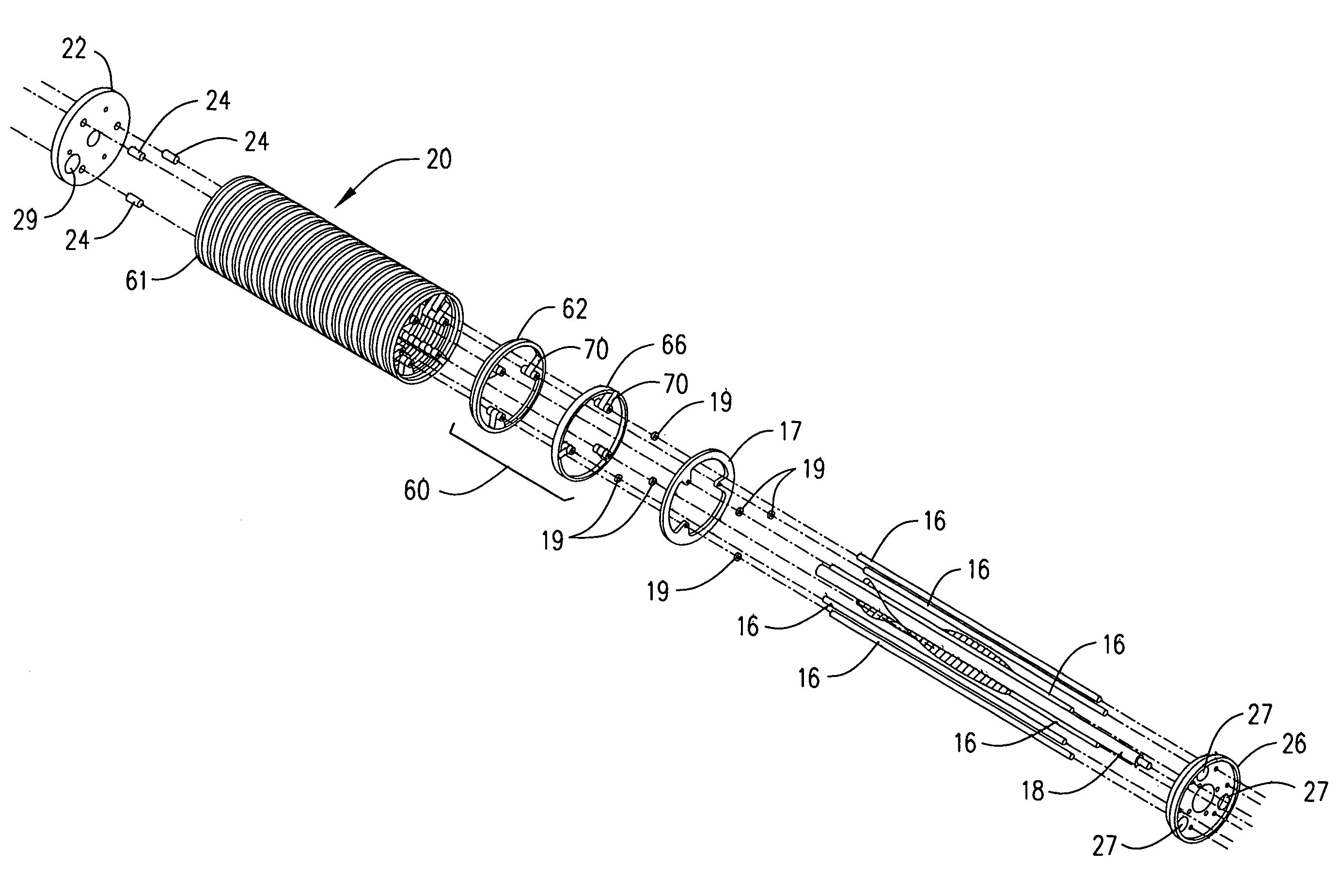
[0006]The current invention provides an improved ring assembly for use in an improved sheller. The improved ring assembly requires less time to assemble and disassemble. The improved ring assembly comprises a plurality of ring units wherein each ring unit has an inner and an outer ring. Each inner and outer ring carries integrally formed spacers. Thus, the current invention eliminates a significant number of components normally requiring assembly during manufacture of the sheller. The sheller also includes a ring adjustment assembly. The ring adjustment assembly provides the means for setting a gap between the inner and outer rings of the ring assembly. The sheller of the current invention also includes conventional drive mechanisms necessary to rotate the ring assembly and a beater bar.
[0009]The current invention significantly reduces the number of parts requiring assembly. By eliminating the separate spacers from the ring assembly, a sheller of the current invention, having eleven ring units with three arms per ring, utilizes 66 fewer parts compared to a prior art sheller. Current invention shellers, having nineteen ring units with three arms per ring, will use 114 fewer parts than a prior art sheller. Thus, the current invention significantly reduces the time required to manufacture the sheller. Additionally, the reduction of individual parts simplifies the disassembly and maintenance of the sheller.

Problems solved by technology

Although the cracking process frees approximately 25-50% of the pecans completely from their shells, the remaining pecans still carry an undesirable woody portion of the shell.
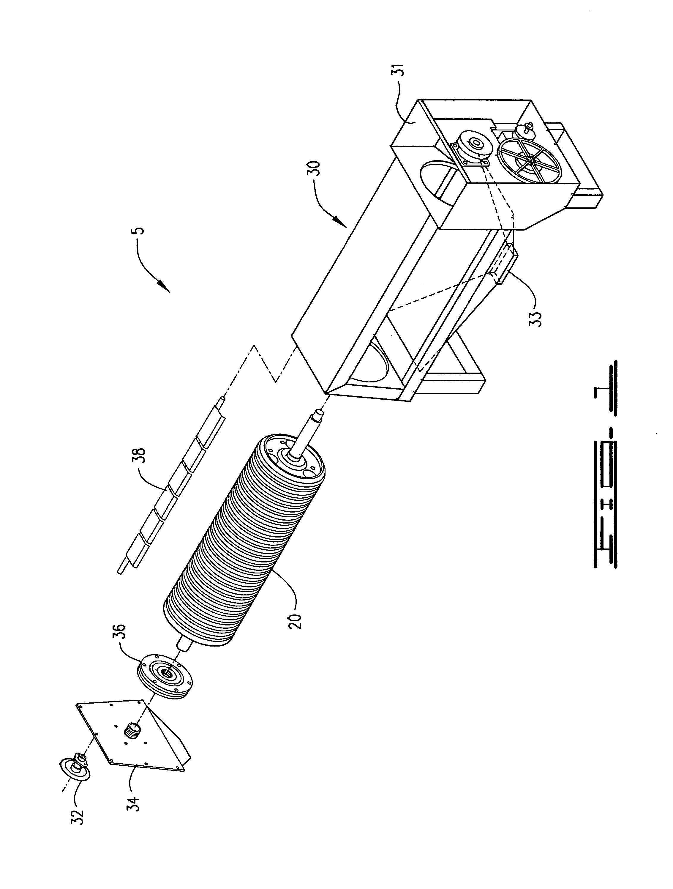
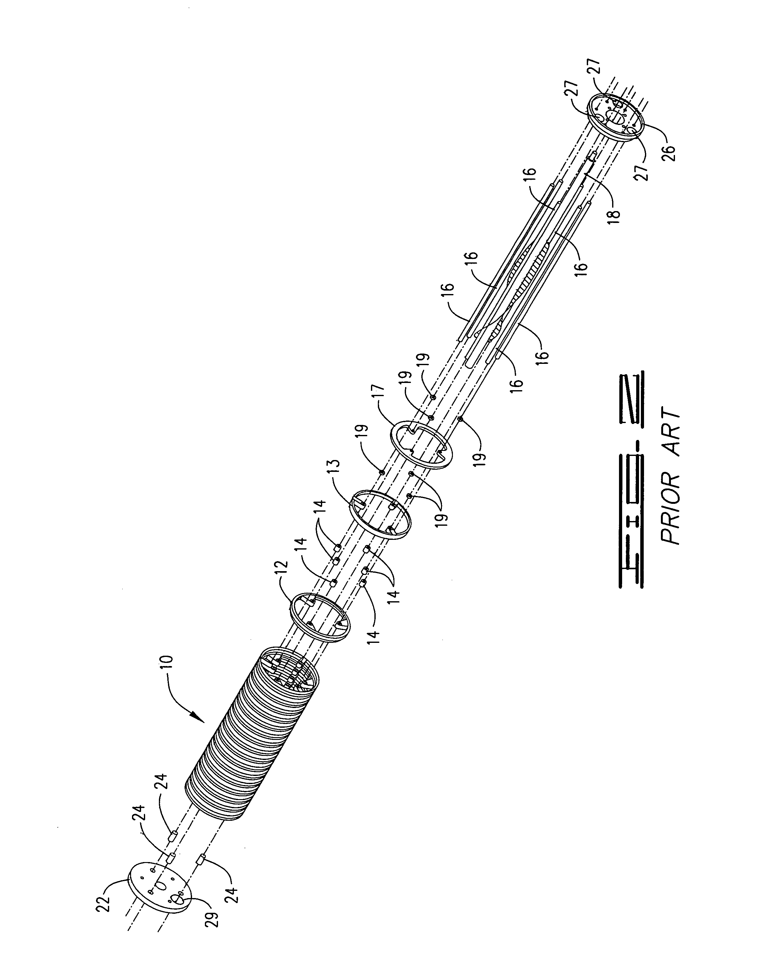
While available shellers provide a quality product, current designs are difficult to assemble and maintain due to the number of components in the ring assembly. FIG. 1 depicts a typical sheller unit 5 and FIG. 2 depicts a prior art ring assembly 10 currently used in sheller 5.

Method used


Image

  • Sheller
  • Sheller
  • Sheller

Examples


Embodiment Construction

[0029]The current invention provides improvements to sheller 5 of the type depicted in FIG. 1. In particular, the current invention replaces prior art ring assembly 10 with an improved ring assembly 20. As shown in FIG. 2, prior art ring assembly 10 includes prior art inner rings 12, prior art outer rings 13, individual spacers 14 and rods 16. Manufacture of prior art ring assembly 10, requires positioning of each inner ring 12, outer ring 13 and spacers 14 on rods 16. Since three spacers 14 are associated with each inner ring 12 and outer ring 13, manufacture of ring assembly 10 is a multi-step, time intensive job. Located to the interior of ring assembly 10 is a beater bar 18. Ring assembly 10 and beater bar 18 are positioned within the housing 30 of sheller 5. Ring assembly 10 also includes a spacer 17 and washers 19 located between outer ring 13 and sprocket 26. As will be described below, ring assembly 20 of the current invention provides improvements to sheller 5 by eliminatin...


PUM


Abstract

The current invention provides an improved sheller for removing the husk or shell from nuts, legumes and other similar plant products. The sheller of the current invention includes an improved ring assembly. The improved ring assembly comprises ring units having an inner ring and an outer ring. Each inner ring carries integrally formed spacers and each outer ring carries integrally formed spacers. Each inner ring directly contacts an adjunct inner ring and each outer ring directly contacts an adjacent outer ring. Through use of integrally formed spacers, the current invention significantly reduces the number of component requiring assembly during the manufacture of the sheller.

Description

[0001]The current invention relates to an improved sheller for removing shell or husk fragments from the meat of a tree nut, a legume or other similar plant products. The improved sheller is particularly useful for removing shell fragments from pecans and walnuts. For the sake of clarity, the following disclosure will focus primarily on the shelling of pecans.[0002]As is known to those skilled in the art, preparation of clean, readily edible pecans requires many steps. Following harvest, pecans are normally sized and cracked. Although the cracking process frees approximately 25-50% of the pecans completely from their shells, the remaining pecans still carry an undesirable woody portion of the shell. To provide the desired product, further processing is normally carried out in a sheller.[0003]A typical sheller houses a rotating assembly comprising a beater bar and a ring assembly. Pecans enter the sheller, passing to the interior of the ring assembly and encounter the beater bar. The...

Claims


Application Information

Patent Timeline
Patent Type & Authority Patents(United States)
IPC IPC(8): A23N5/00A47J43/00
CPCA23N5/00A23N5/08
Inventor SAVAGE, BASIL W.
Owner SAVAGE EQUIP
Learn More