Walker wedge

a technology for walker wedges and users, which is applied in the direction of wheelchairs/patient conveyances, wheelchairs, transportation and packaging, etc., can solve the problems of a relatively large gap between the posterior of the seat user and the seat user, and achieve the effect of increasing density and thickness, convenient use, and easy adjustment of the level of compressibility of foam

Inactive Publication Date: 2008-11-04
TRAC TEC
View PDF12 Cites 15 Cited by
  • Summary
  • Abstract
  • Description
  • Claims
  • Application Information

AI Technical Summary

Benefits of technology

[0007]This invention achieves those requirements. The invention is a molded foam spinal support device that is easy to use, provides the ability to produce the desired isolated force on the sacrum, yet permits easy adjustment of the level of compressibility of the foam. Additionally, the present invention also achieves its effectiveness in being able to correctly position a user's sacrum in a variety of types of seats.
[0008]The molded device includes a main body, having a central portion and outwardly directed wing portions. The main body can be used by itself or with one of a number of inserts, each offering varying degrees of increasing density and thickness. As inserts having increasing density are used within the central portion of the main body, that central area of the main body where the selected insert is placed will become less and less compressible. This progressively increases the force that can applied to the user's sacrum, thereby resulting in increasing levels of support for the sacrum. The desired level for such an applied, and isolated, force should be enough to properly position the sacrum, yet not so much as might result in pain or discomfort to the user. The proper level of compression or density will that which will make the support device virtually disappear as an additional seat component. Additionally, the main body is designed to permit those portions of the body adjacent the sacrum to be relatively less supported. While the sacrum itself needs to be supported, the adjacent body structure will desirably be able to move rearwardly, or fall back, by an amount needed to achieve the desired level of pelvic pivot to properly orient the spine.

Problems solved by technology

It was found that with many types of seating, for example, automotive seats, there is usually a relatively large gap between the posterior of the seat user and the area where the bottom and back portions of such seats join or are connected together.

Method used


Image

  • Walker wedge
  • Walker wedge
  • Walker wedge

Examples


Embodiment Construction

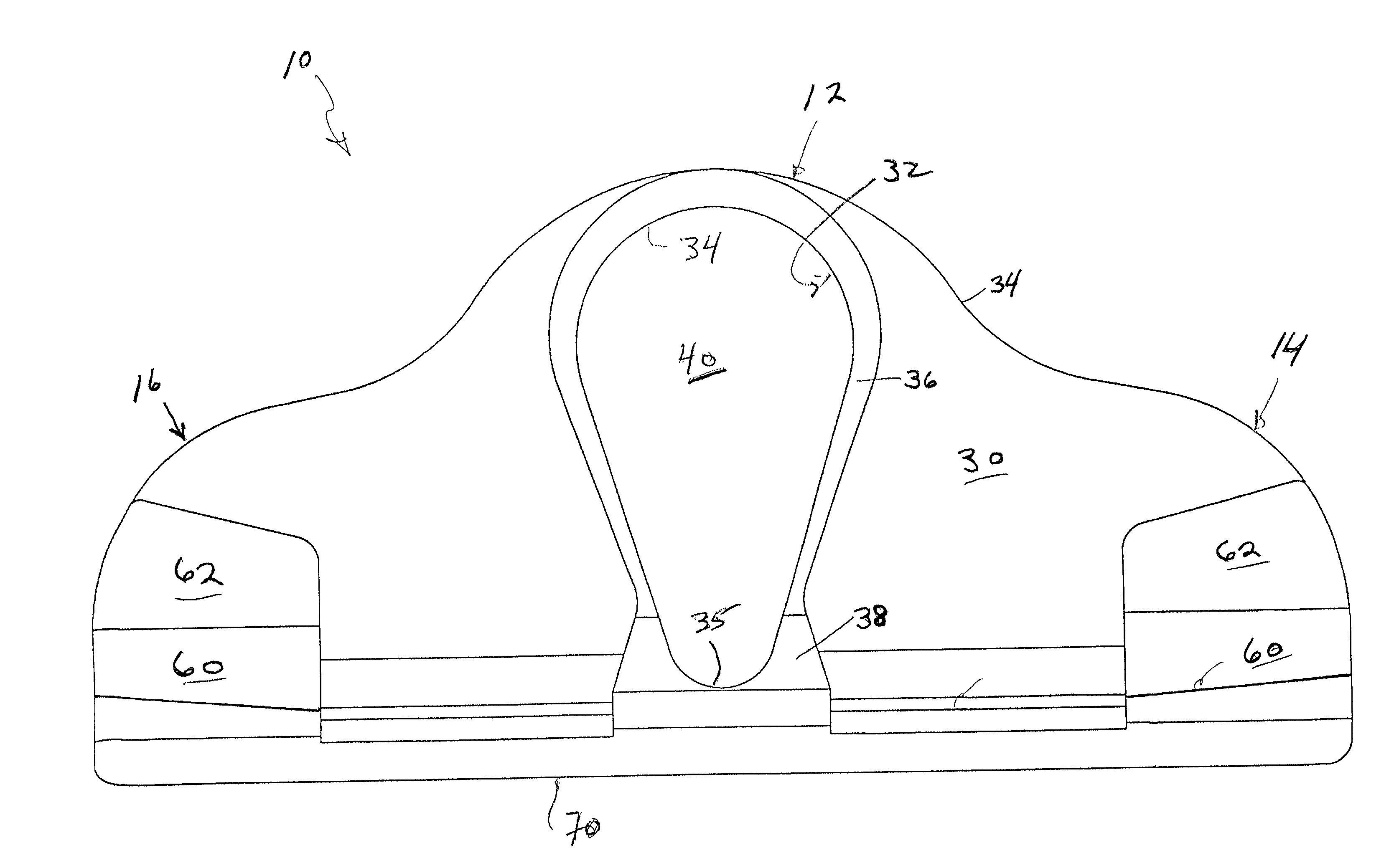
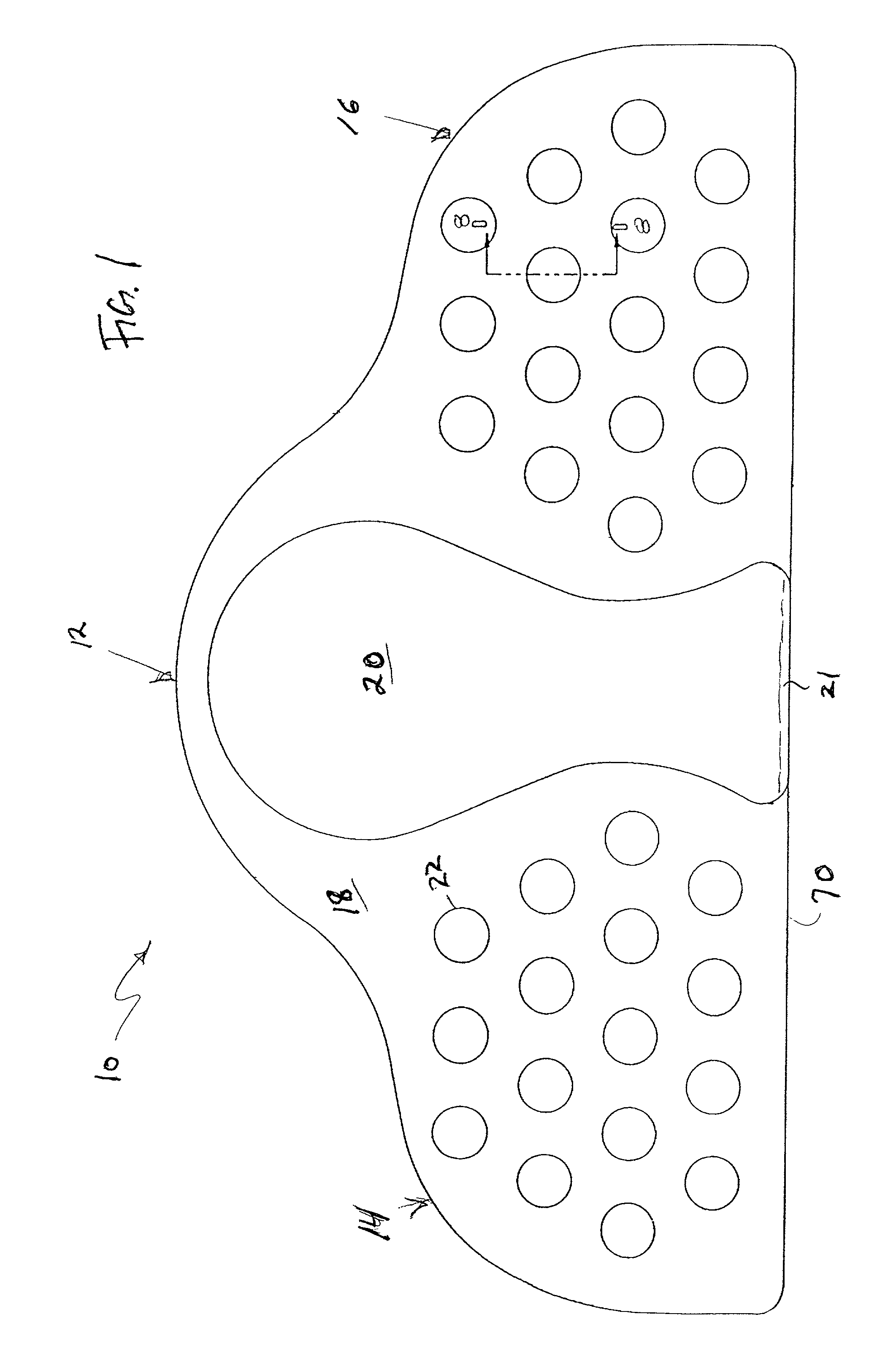
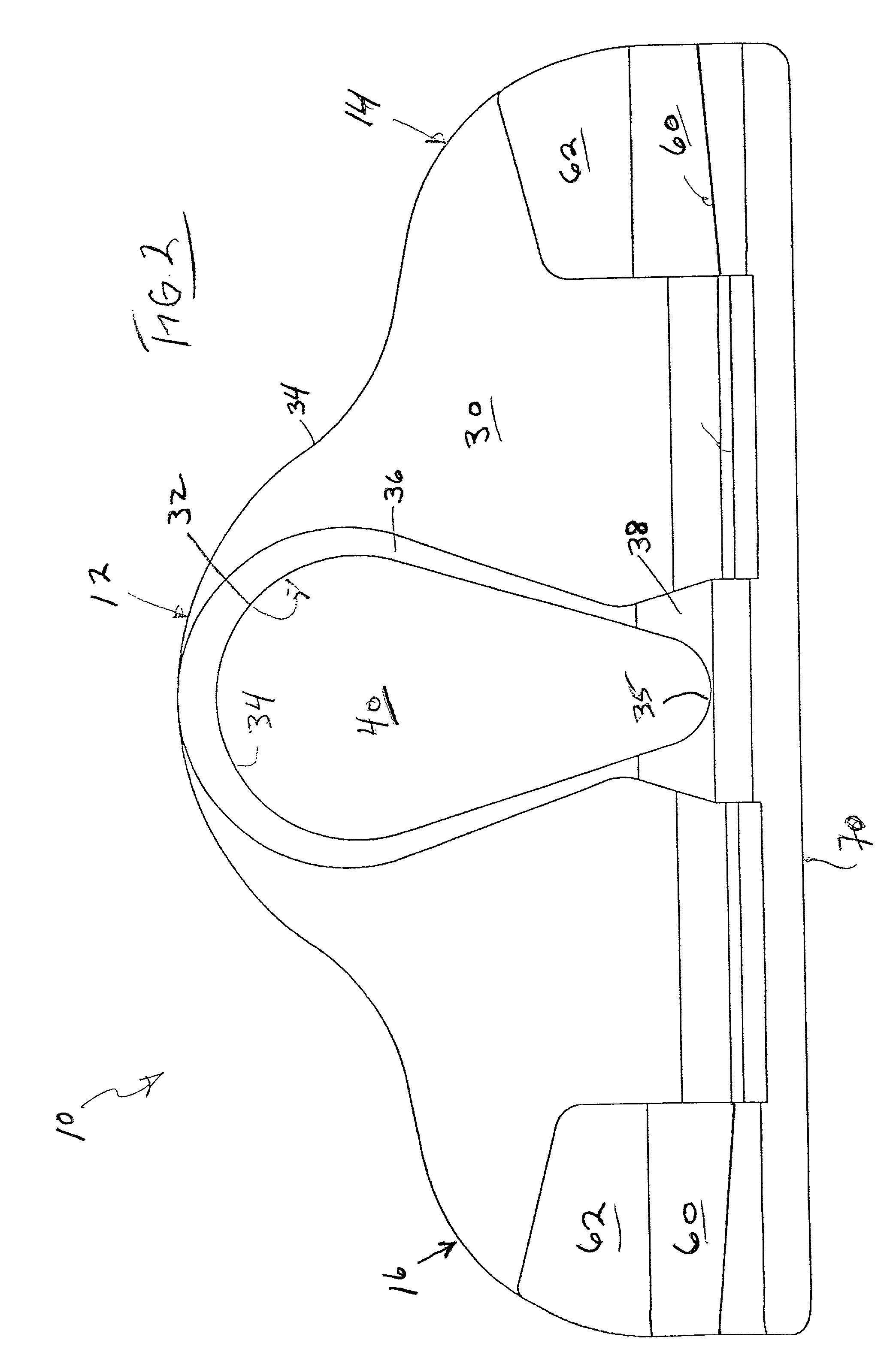
[0027]Turning to the drawings, principally FIGS. 1-4, the main body of the support device, generally shown at 10, includes a central area 12, left and right end or wing areas 14 and 16, respectively, and a bottom 70. It is preferred that the support device be a molded product that is formed from one of a number of conventional molding techniques. The front face 18 is formed to have a vertically and horizontally extending curvature, and includes a raised or protruding area 20 provided as the main part of the front surface in the central area 12. The front surface of each of the left and right areas 14 and 16, located on either side of the raised area 20, include a plurality of dimples or recesses 22. These dimples are provided to not only aid in making the front surface non-slip, but to make the device comfortable in use and to control the level of compression of the foam material. Such a recess 22 is shown in FIG. 8 with a depth of about 0.15 inches and a diameter of about 0.2 to ab...


PUM


Abstract

A cushion for use with a variety of types of seats, for example, automotive seats, to adjust the sacrum thereby pivoting the pelvis to assist in maintaining the spine in equilibrium. The cushion is preferably separate from the seat and has central and end support areas that have a density or compressibility that is greater than that of the interconnecting portions. The central area is also provided with one of a plurality of inserts that individually have varying compressibility so that the compressibility of the central area is variable by changing between the inserts.

Description

BACKGROUND OF THE INVENTION[0001]1. Field of the Invention[0002]The present invention relates to a spine orienting device for use with a variety of types of seats, for example, automotive seats or office type seating, in order to properly position the sacrum, which in turn will properly position the spine of the individual using the seat. The spine orienting device, preferably made from foam, can include a plurality of interchangeable inserts, each having differing densities, or a device that could, by itself, provide a variety of variable compression results. Through the use of such inserts or devices, a user can use the device by itself or select one insert, or perhaps more than one insert, most suited to the user and the seat to provide a compression result that will provide sufficient pressure concentrate on the sacrum of the user to properly position the sacrum. The device will also fill an otherwise empty space between the bottom and rear seat sections, thereby further improvi...

Claims


Application Information

Patent Timeline
Patent Type & Authority Patents(United States)
IPC IPC(8): A61G15/00
CPCA47C7/021A47C27/00A47C27/20B60N2/646A61G2005/1091B60N2205/40A61G5/1091
Inventor WALKER, BROCK M
Owner TRAC TEC
Why Eureka
Try Eureka