
Fluid control structures in microfluidic devices

a technology of fluid control structure and microfluidic device, which is applied in the direction of flow mixer, multi-way valve, shaking/oscillating/vibrating mixer, etc., can solve the problems of difficult fabrication of microfluidic control elements in dense arrays, chemical or biochemical assays that cannot be easily analyzed, and limited conventional mechanisms for microfluidic analysis

Active Publication Date: 2008-11-04
RGT UNIV OF CALIFORNIA
View PDF32 Cites 200 Cited by
  • Summary
  • Abstract
  • Description
  • Claims
  • Application Information

AI Technical Summary

Problems solved by technology

Conventional mechanisms for microfluidic analysis are limited.
However, many microfluidic analysis devices that include fluidic control capabilities are chemically or physically incompatible with many chemical or biochemical assays.
In addition, many microfluidic control elements are difficult to fabricate in dense arrays because of limitations in the fabrication process, robustness, and / or design.
A microfluidic device utilizing such valves can not be removed from its control system without losing control of the fluidic contents of the device.
In addition, many techniques and mechanisms for microfluidic analysis furthermore lack sensitivity, specificity, or quantitative analysis capabilities.
In particular, conventional microfluidic analysis mechanisms lack the functionality and capabilities to efficiently implement sample preparation for systems such as pathogen detectors and analyzers.

Method used


Image

  • Fluid control structures in microfluidic devices
  • Fluid control structures in microfluidic devices
  • Fluid control structures in microfluidic devices

Examples


Embodiment Construction

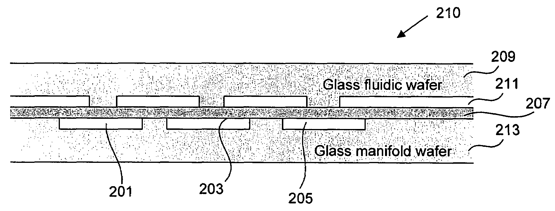
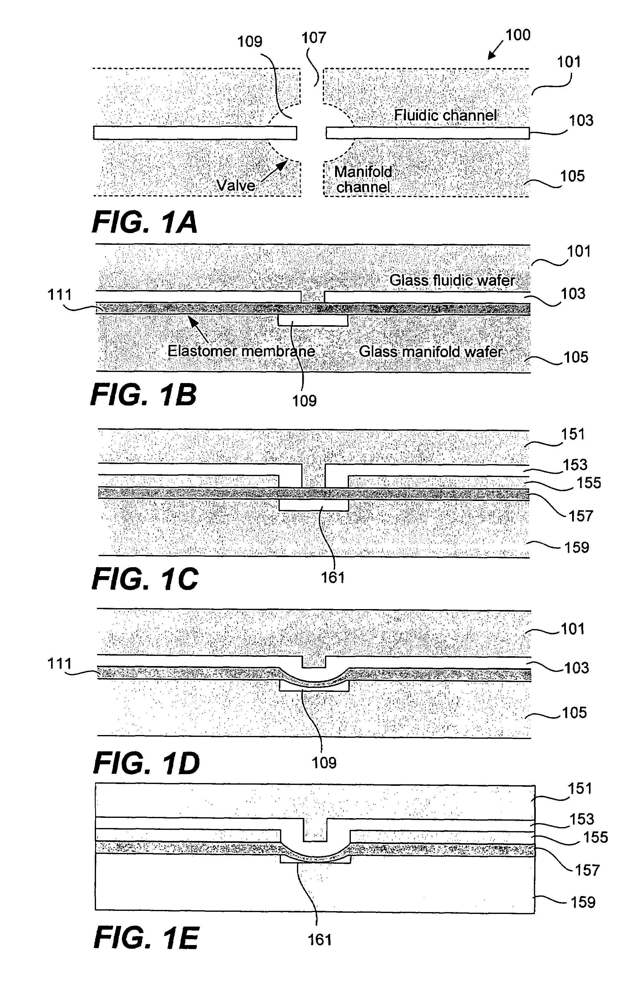
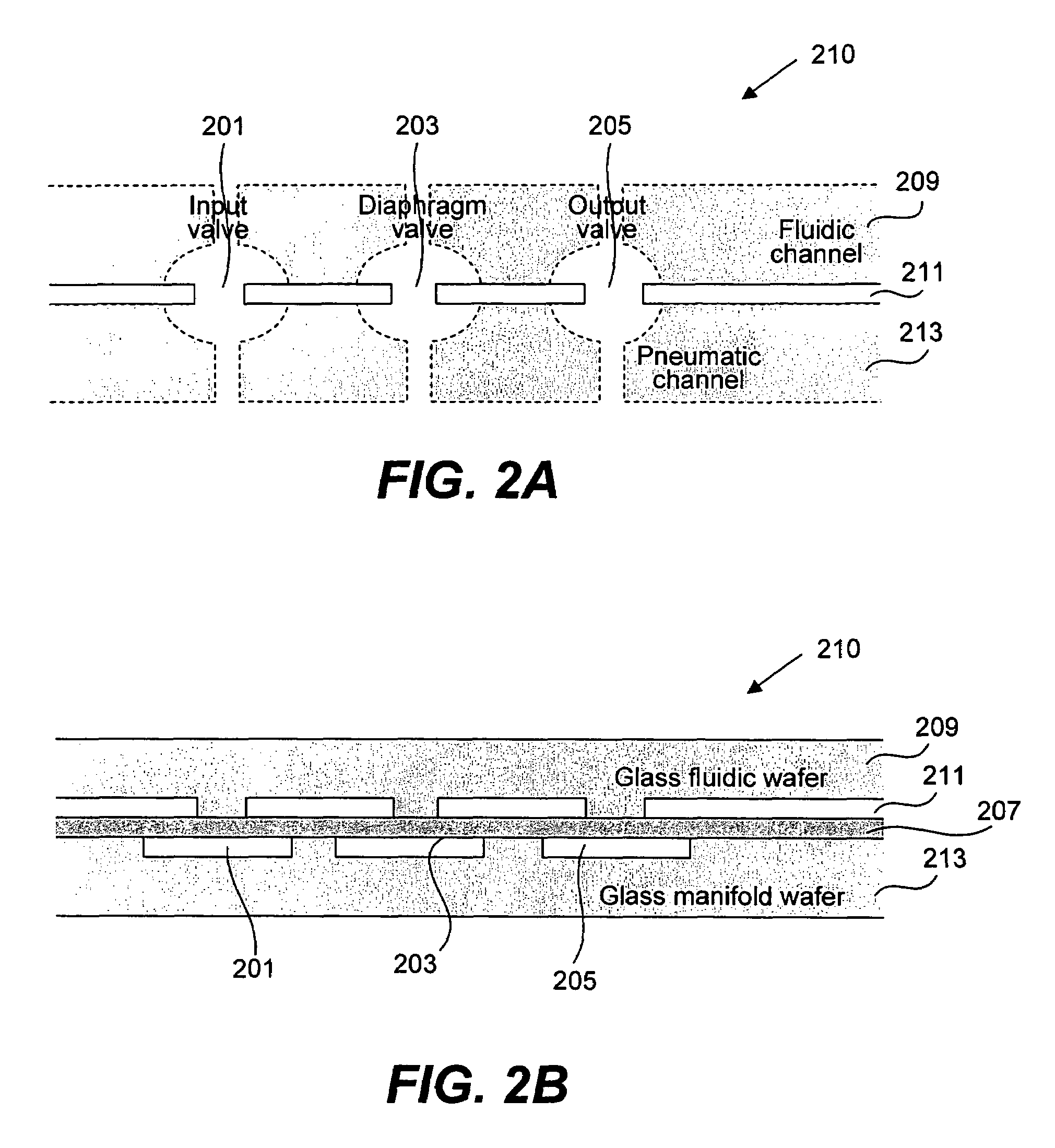
[0028]Reference will now be made in detail to some specific embodiments of the invention including the best modes contemplated by the inventors for carrying out the invention. Examples of these specific embodiments are illustrated in the accompanying drawings. While the invention is described in conjunction with these specific embodiments, it will be understood that it is not intended to limit the invention to the described embodiments. On the contrary, it is intended to cover alternatives, modifications, and equivalents as may be included within the spirit and scope of the invention as defined by the appended claims. For example, the techniques of the present invention will be described in the context of glass microfluidic devices, although other devices such as plastic devices could also be used.

[0029]It should be noted that the fluid control structures suitable for use in glass microfluidic devices can be applied to a variety of microfluidic devices. A pathogen detection system i...


PUM

PropertyMeasurementUnit
thickaaaaaaaaaa
thickaaaaaaaaaa
thickaaaaaaaaaa

Abstract

Methods and apparatus for implementing microfluidic analysis devices are provided. A monolithic elastomer membrane associated with an integrated pneumatic manifold allows the placement and actuation of a variety of fluid control structures, such as structures for pumping, isolating, mixing, routing, merging, splitting, preparing, and storing volumes of fluid. The fluid control structures can be used to implement a variety of sample introduction, preparation, processing, and storage techniques.

Description

CROSS REFERENCE To RELATED APPLICATIONS[0001]This application claims priority under U.S.C. 119(e) from Provisional U.S. Patent Application Ser. No. 60 / 475,013 filed May 30, 2003, titled “Monolithic Membrane Structures for Fluid Control in Glass Microfluidic Devices”, and from Provisional U.S. Patent Application Ser. No. 60 / 437,262 filed Dec. 30, 2002, titled “Microfabricated Immuno-Genetic Pathogen Analyzer,” the entireties of which are incorporated by reference for all purposes. This application is also related to concurrently filed PCT Application No. PCT / US03 / 41466, filed Dec. 29, 2003, titled “Microfabricated Immuno-Genetic Pathogen Analyzer,” the entirety of which is incorporated by reference for all purposes.STATEMENT REGARDING FEDERALLY SPONSORED RESEARCH[0002]The techniques and mechanisms of the present invention were made with Government support under Contract DEFG91ER61125 by the U.S. Department of Energy, by NASA Grant No. NAG5-9659, and by NIH grants HG01399 and P01 CA 7...

Claims


Application Information

Patent Timeline
Patent Type & Authority Patents(United States)
IPC IPC(8): C12M1/34B01L11/00F15C1/06B01L3/00B01L7/00B01L99/00B32B27/04C07H21/02C12NC12P19/34C12Q1/68
CPCB01F5/10B01F11/0071B01F13/0059B01L3/502707B01L3/50273B01L3/502738C12Q1/6806C12Q1/689F04B43/043F04B43/06F16K99/0001B01L3/5025B01L7/52B01L2200/10B01L2300/0654B01L2300/0803B01L2300/0816B01L2300/0819B01L2300/0861B01L2300/087B01L2300/088B01L2300/0887B01L2300/1827B01L2400/0409B01L2400/0421B01L2400/0487B01L2400/0638B01L2400/0655C12Q2565/629G01N35/00069Y10T137/87716Y10T137/2224Y10T137/0318B01L2300/123B01F25/50B01F31/65B01F33/30C12M1/34G01N35/08G01N33/48
Inventor MATHIES, RICHARD A.GROVER, WILLIAM H.SKELLEY, ALISONLAGALLY, ERICLIU, CHUNG N.
Owner RGT UNIV OF CALIFORNIA
Learn More