Optical switch, and apparatus and method for controlling optical switch

a technology of optical switch and protuberance, which is applied in the direction of optical elements, multiplex communication, instruments, etc., can solve the problems of preventing the system structure from having high freedom and the s/n ratio degrade, and achieve the effect of reducing the quantity of protuberance, high freedom, and signal quality in all bands

Inactive Publication Date: 2008-11-04
FUJITSU LTD
View PDF8 Cites 11 Cited by
  • Summary
  • Abstract
  • Description
  • Claims
  • Application Information

AI Technical Summary

Benefits of technology

[0033](5) The mirror may be operable about two axes so as to be able to change the angle of the reflecting surface thereof in the direction in which the mirrors are arranged and a direction in which the output ports are arranged, which is perpendicular to the direction in which the mirrors are arranged, and, when the incident position of the reflected beam irradiated onto any one of the output ports is changed to another output port not adjacent to the output port, the mirror controlling means may control the angle of the reflecting surface of the mirror in such a manner that the mirror controlling means controls the angle of the reflecting surface of the corresponding mirror in the direction in which the output ports are arranged to move the incident position of the reflected beam toward an adjacent output port, and combines controls on the angle of the reflecting surface of the mirror in the direction in which the mirrors are arranged and the direction in which the output ports are arranged so as to move the incident position to the another output port.
[0044]Particularly, since the band characteristic can be flat, it is possible to make the optical levels of wavelengths (channels) allocated to bands uniform, thus the signal quality in all bands of a wavelength-multiplexed beam can be improved.

Problems solved by technology

This causes degradation of the S / N ratio.
This becomes noticeable in multi-stage connections, which limits the number of the multi-stage connections, preventing the system structure from having high freedom.

Method used


Image

  • Optical switch, and apparatus and method for controlling optical switch
  • Optical switch, and apparatus and method for controlling optical switch
  • Optical switch, and apparatus and method for controlling optical switch

Examples


first modification

(A1) First Modification

[0082]When the above MEMS mirror 4 is configured as a MEMS mirror of a double-side swinging type, that is, the mirror angle thereof can be changed right and left in the horizontal direction (wavelength dispersion direction) as shown in FIG. 8(B), the input port 21 and the output ports 22 can be arranged as shown in FIG. 8(A), for example. Namely, ten output ports 22 (22a through 22j) are arranged in two arrays for one input port 21. Each of the arrays can be in a direction perpendicular to the wavelength dispersion direction. In this modification, a distance between the output ports 22 and a distance between the arrays are designed (set) on the basis of the designed attenuation level and the allowable crosstalk level, as described above with reference to FIGS. 6 and 7.

[0083]When the reflected beam irradiated onto an output port 22 in the first row in the right array is desired to be irradiated onto an output port 22 in the fourth row in the left array as shown...

second modification

(A2) Second Modification

[0087]When the MEMS mirror 4 is a MEMS mirror of a single-side swinging type where the mirror angle can be change only right or left in the wavelength dispersion direction as shown in FIG. 9(B), one input port 21 and nine output ports 22 (22a through 22i) totaling ten are arranged in two arrays. In this case, the distance between output ports 22 in each array and the distance between the arrays are designed (set) on the basis of the designed attenuation level and the allow able crosstalk level, like the example described above with reference to FIGS. 6 and 7.

[0088]When the reflected beam irradiated onto an output port 22e in the first row in the left array is desired to be irradiated onto the fourth output port 22c in the right array as shown in FIG. 9(A), the controlling apparatus 50 changes the mirror angle of a corresponding MEMS mirror 4 in the vertical direction to direct the beam position of the reflected beam irradiated onto the output port 22e toward ...

third modification

(A3) Third Modification

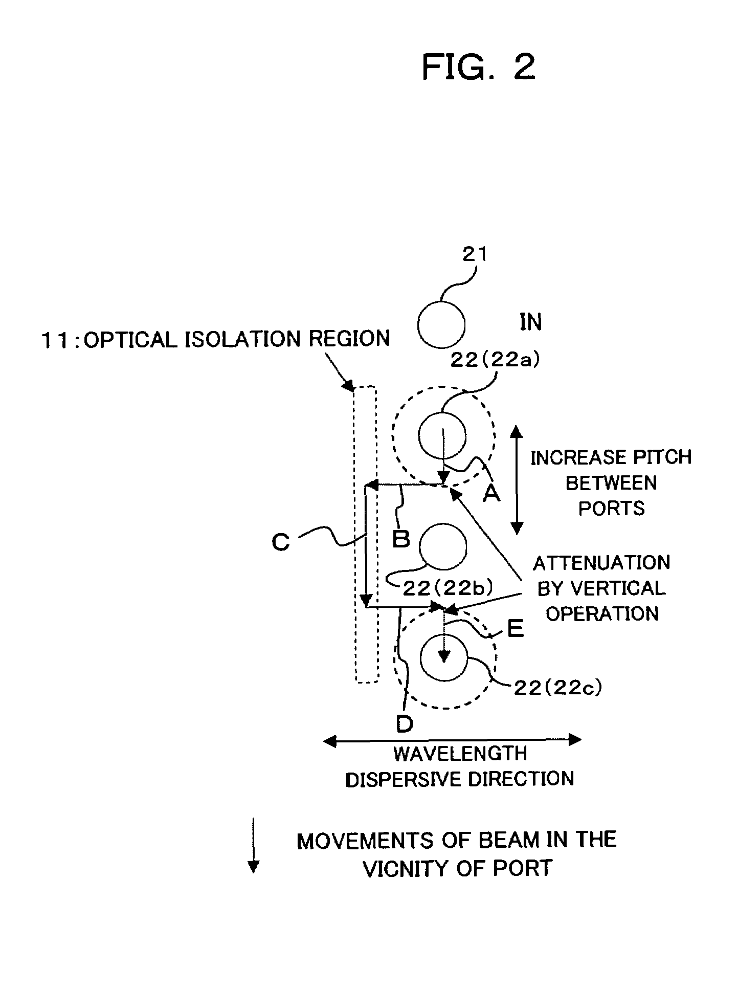
[0091]In the above embodiment and modifications, the controlling apparatus 50 moves the beam position from an output port 22, from which the beam is moved, into the optical isolation region 11, or moves the beam position from the optical isolation region 11 to a target output port 22, by changing once the mirror angle in the horizontal direction. However, as shown in FIG. 10, the quantity of a change in the mirror angle at a time may be made minute and the quantity of movement of the beam at a time may be made minute, and the mirror angel of the MEMS mirror 4 may be changed plural times alternately in the vertical and horizontal directions, whereby the beam position is moved step-wise during a course from the starting output port 22a to the optical isolation region 11, or from the optical isolation region 11 to the target output port 22c.

[0092]By doing so, it is possible to further shorten the pitch between ports as compared with a case where the control is p...


PUM


Abstract

In an optical switch comprising a wavelength spatially dispersive optical element for spatially dispersing a wavelength-multiplexed beam according to wavelengths, a plurality of output ports and a plurality of mirrors onto which beams dispersed by the element are irradiated, and each of which is able to direct a reflected beam to any one of the plural output ports, when an incident position of a reflected beam irradiated onto any one of the output ports is changed, the angle of the reflecting surface of a corresponding mirror among the plural mirrors is changed in a direction other than a direction in which the mirrors are arranged, whereby a protuberance in the vicinity of the out-band (side lobe) of the transmission band characteristic of the optical switch can be suppressed.

Description

CROSS REFERENCE TO THE RELATED APPLICATIONS[0001]This application is based on and hereby claims priority to Japanese Application No. 2004-376932 filed on Dec. 27, 2004 in Japan, the contents of which are hereby incorporated by reference.BACKGROUND OF THE INVENTION[0002](1) Field of the Invention[0003]The present invention relates to an optical switch, and an apparatus and method for controlling the optical switch. Particularly, the present invention relates to a technique suitable for use at the case where an optical path is deflected by changing an angle of a reflecting surface to direct a reflected beam to any one of a plurality of output ports.[0004](2) Description of Related Art[0005]Heretofore, switching of channels in an optical transmission system is performed by means of an electric switch after an optical signal is converted into an electric signal. However, use of a switch (optical switch) for switching an optical signal as it is without converting the optical signal into ...

Claims


Application Information

Patent Timeline
Patent Type & Authority Patents(United States)
IPC IPC(8): G02B6/26
CPCG02B6/2931G02B6/29311G02B6/29313G02B6/29395G02B6/3512G02B6/355G02B6/3556G02B6/356
Inventor AOTA, HIROFUMIAKASHI, TAMOTSU
Owner FUJITSU LTD
Why Eureka
Try Eureka