Method and apparatus for the transmission fault detection in an access network

a technology of optical access network and transmission fault, applied in the field of optical access network, can solve the problems of incomplete data transmission to the olt, inability to remotely identify the fault, and inability to provide data to users at the rate required by those high bit rate applications, etc., and achieve the effect of rapid identification

Active Publication Date: 2008-01-22
CIENA
View PDF5 Cites 12 Cited by
  • Summary
  • Abstract
  • Description
  • Claims
  • Application Information

AI Technical Summary

Benefits of technology

[0009]It is therefore an object of the invention to provide a method and system for rapidly identifying a faulty ONU in an access network interconnected by passive optical network (PON) equipment.
[0011]Advantageously the secondary modulation can be switched off during a timeslot allotted to the ONU, using timeslot information available at the ONU, and switching means. By switching the secondary modulation off in this interval, a signal quality penalty associated with superposition of the secondary modulation on the primary or data modulation can be avoided.

Problems solved by technology

However, the delivery of data to users at rates required by those high bit rate applications is generally not supported.
The last mile problem is directed to providing efficiently upgradeable high bandwidth service to residential and small commercial users at a price that makes the services appealing to a wide audience.
Because of the shared use of the optical fiber, and the absence of electrical signal reception equipment in the access network, a problem can arise with ONU transmission equipment in such a configuration.
This results in a complete blockage of data transmission to the OLT.
Since all of the ONUs share the return data channel wavelength, and an ONU laser can lapse into the error state at any time, there is no way to remotely identify the faulty ONU.
Throughout this time, the return data channel remains unusable, resulting in inconvenienced customers.

Method used


Image

  • Method and apparatus for the transmission fault detection in an access network
  • Method and apparatus for the transmission fault detection in an access network
  • Method and apparatus for the transmission fault detection in an access network

Examples


Embodiment Construction

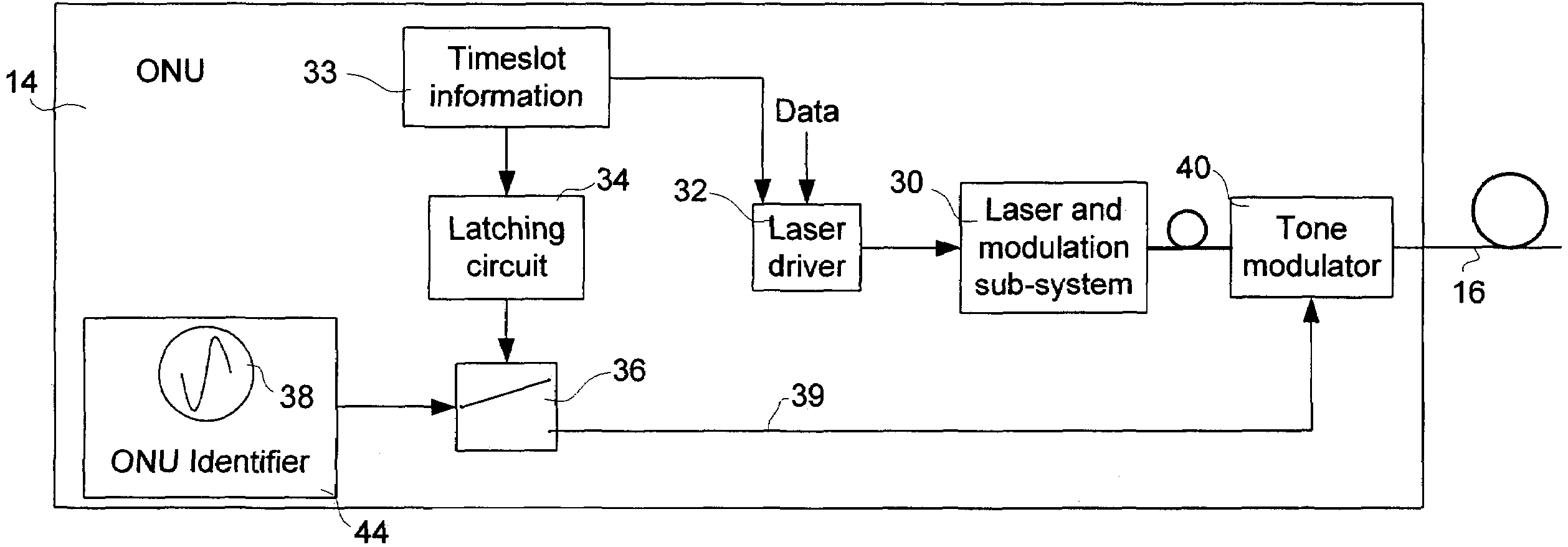
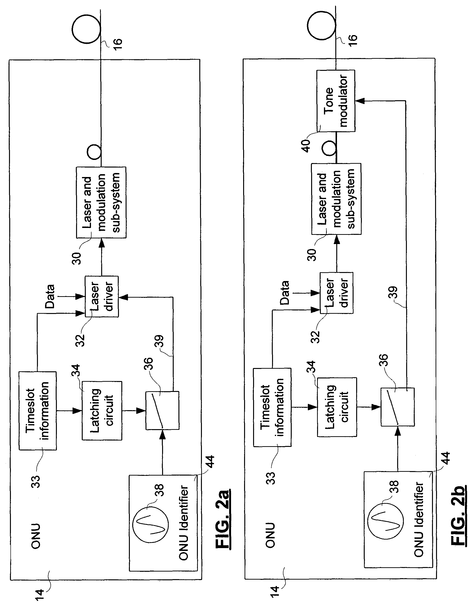
[0025]The invention provides a method for identifying an optical network unit (ONU) in a passive optical network (PON) that is in a transmission failure state, such as a laser that is stuck in the “on” state, which interferes with transmissions by other ONUs in the PON.

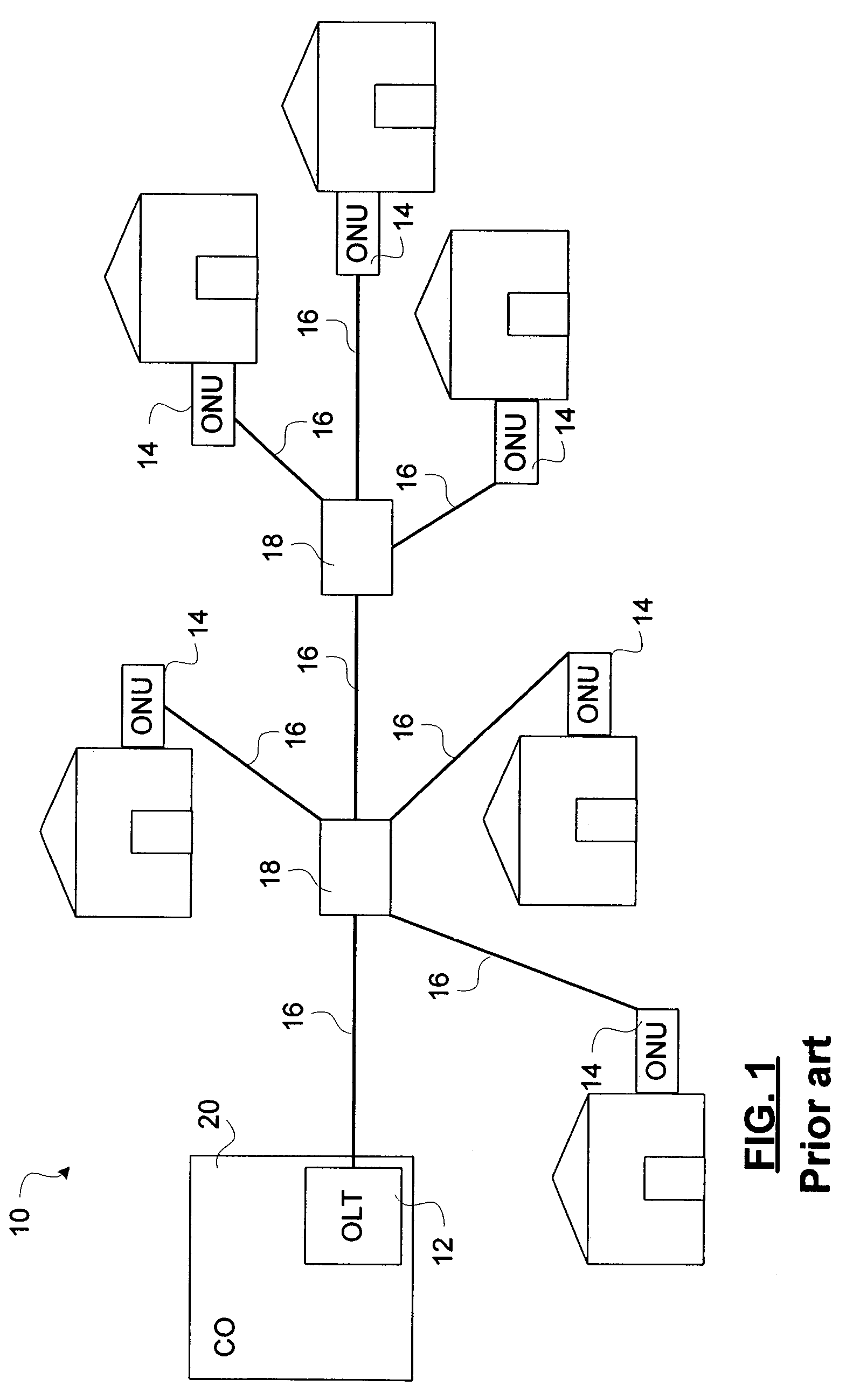
[0026]As schematically shown in FIG. 1, the topology of a PON 10 is that of a tree structure. The root of the tree structure is the optical line terminal (OLT) 12, from which branches extend to interconnect ONUs 14. The branches are fiber optic links 16 that are connected to passive optical equipment, such as passive optical splitter 18. In the illustrated embodiment, the PON 10 includes 6 ONUs 14, interconnected by 8 fiber optic links and 2 passive optical splitters 18.

[0027]Each of the ONUs 14 serves a respective subscriber unit, which may be residential customer premise equipment such as networked computing devices. The connections between the subscriber units and ONUs 14 may be fiber optic links, coaxial cable, or...


PUM


Abstract

An optical network unit (ONU) interconnected by passive optical network (PON) equipment to an optical line terminal (OLT) is identified using secondary modulation of the optical carrier to impress an identifier of the ONU onto the carrier. This resolves a recurring ONU failure mode detection problem caused by failure of a laser driver that causes the ONU to be stuck in an on state.

Description

CROSS-REFERENCE TO RELATED APPLICATIONS[0001]This application claims the benefit under 35 USC § 119(e) of U.S. Provisional Application 60 / 445,837, filed Feb. 6, 2003.MICROFICHE APPENDIX[0002]Not Applicable.TECHNICAL FIELD[0003]The invention generally relates to optical access networks, and, in particular, to a method and apparatus for detecting transmission faults in an optical access network.BACKGROUND OF THE INVENTION[0004]The development of optical networking, and technologies for wavelength division multiplexing (WDM) of data onto optical fibers, has provided a high capacity communication network backbone that is capable of supporting high bit rate applications. However, the delivery of data to users at rates required by those high bit rate applications is generally not supported. This is referred to as the “last mile problem”. The last mile problem is directed to providing efficiently upgradeable high bandwidth service to residential and small commercial users at a price that m...

Claims


Application Information

Patent Timeline
Patent Type & Authority Patents(United States)
IPC IPC(8): H04J14/00H04B10/08H04B10/14H04B10/02H04J14/02
CPCH04B10/0779H04J14/0227H04J14/0258H04J14/0282H04J14/0298H04Q11/0067H04J14/0232H04J14/0245H04J14/0249H04B2210/08H04Q2011/0083
Inventor FELSKE, KENTBRAND, RICHARDBERNIER, ERIC
Owner CIENA
Why Eureka
Try Eureka