Optical switch, and apparatus and method for controlling optical switch
a technology of optical switch and protuberance, which is applied in the direction of optical elements, multiplex communication, instruments, etc., can solve the problems of preventing the system structure from having high freedom and the s/n ratio degrade, and achieve the effect of reducing the quantity of protuberance, high freedom, and signal quality in all bands
- Summary
- Abstract
- Description
- Claims
- Application Information
AI Technical Summary
Benefits of technology
Problems solved by technology
Method used
Image
Examples
first modification
(A1) First Modification
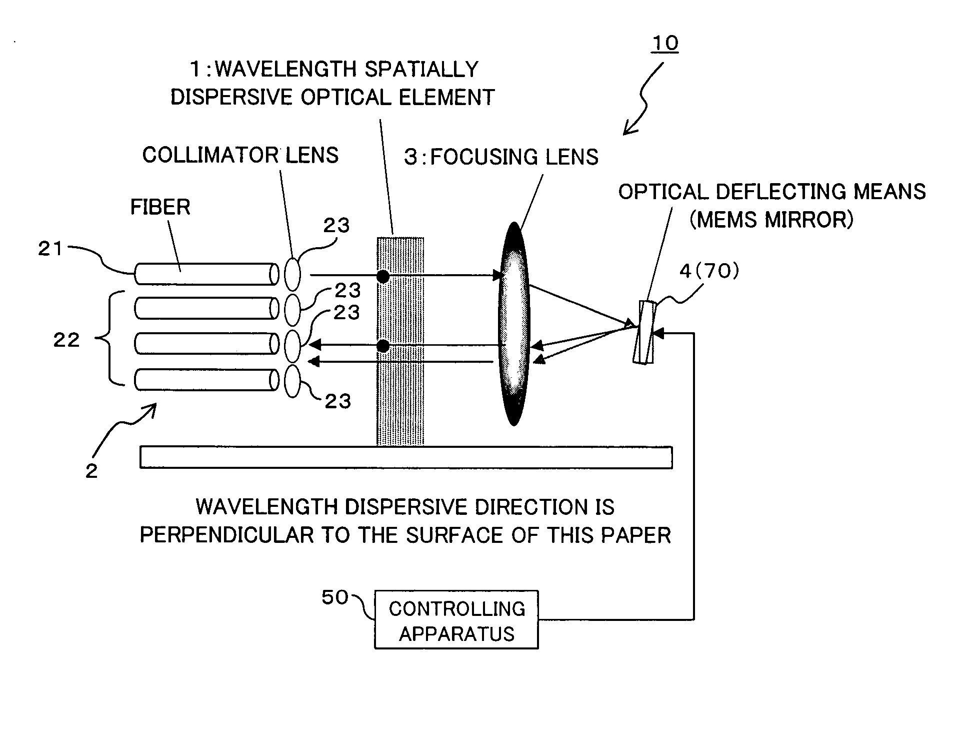
[0082] When the above MEMS mirror 4 is configured as a MEMS mirror of a double-side swinging type, that is, the mirror angle thereof can be changed right and left in the horizontal direction (wavelength dispersion direction) as shown in FIG. 8(B), the input port 21 and the output ports 22 can be arranged as shown in FIG. 8(A), for example. Namely, ten output ports 22 (22a through 22j) are arranged in two arrays for one input port 21. Each of the arrays can be in a direction perpendicular to the wavelength dispersion direction. In this modification, a distance between the output ports 22 and a distance between the arrays are designed (set) on the basis of the designed attenuation level and the allowable crosstalk level, as described above with reference to FIGS. 6 and 7.
[0083] When the reflected beam irradiated onto an output port 22 in the first row in the right array is desired to be irradiated onto an output port 22 in the fourth row in the left array as sh...
second modification
(A2) Second Modification
[0087] When the MEMS mirror 4 is a MEMS mirror of a single-side swinging type where the mirror angle can be change only right or left in the wavelength dispersion direction as shown in FIG. 9(B), one input port 21 and nine output ports 22 (22a through 22i) totaling ten are arranged in two arrays. In this case, the distance between output ports 22 in each array and the distance between the arrays are designed (set) on the basis of the designed attenuation level and the allow able crosstalk level, like the example described above with reference to FIGS. 6 and 7.
[0088] When the reflected beam irradiated onto an output port 22e in the first row in the left array is desired to be irradiated onto the fourth output port 22c in the right array as shown in FIG. 9(A), the controlling apparatus 50 changes the mirror angle of a corresponding MEMS mirror 4 in the vertical direction to direct the beam position of the reflected beam irradiated onto the output port 22e towa...
third modification
(A3) Third Modification
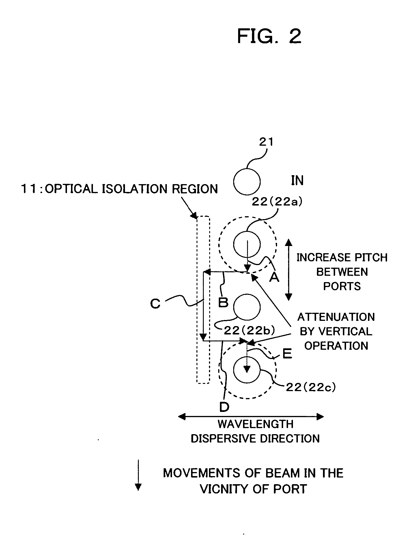
[0091] In the above embodiment and modifications, the controlling apparatus 50 moves the beam position from an output port 22, from which the beam is moved, into the optical isolation region 11, or moves the beam position from the optical isolation region 11 to a target output port 22, by changing once the mirror angle in the horizontal direction. However, as shown in FIG. 10, the quantity of a change in the mirror angle at a time may be made minute and the quantity of movement of the beam at a time may be made minute, and the mirror angel of the MEMS mirror 4 may be changed plural times alternately in the vertical and horizontal directions, whereby the beam position is moved step-wise during a course from the starting output port 22a to the optical isolation region 11, or from the optical isolation region 11 to the target output port 22c.
[0092] By doing so, it is possible to further shorten the pitch between ports as compared with a case where the control is...
PUM
 Abstract
Description
Claims
Application Information
 - R&D
- Intellectual Property
- Life Sciences
- Materials
- Tech Scout
- Unparalleled Data Quality
- Higher Quality Content
- 60% Fewer Hallucinations
Browse by: Latest US Patents, China's latest patents, Technical Efficacy Thesaurus, Application Domain, Technology Topic, Popular Technical Reports.
© 2025 PatSnap. All rights reserved.Legal|Privacy policy|Modern Slavery Act Transparency Statement|Sitemap|About US| Contact US: help@patsnap.com


