Ethernet communications for power monitoring system

a technology of power monitoring and ethernet communication, applied in the field of power monitoring arts, can solve problems such as the inability to communicate with html pages of browsers or other servers

Inactive Publication Date: 2008-11-04
SQUARE D CO
View PDF22 Cites 47 Cited by
  • Summary
  • Abstract
  • Description
  • Claims
  • Application Information

AI Technical Summary

Problems solved by technology

The Ethernet gateway device (EGW) did not include a Hyptertext transfer protocol server, and hence was unable to communicate with HTML pages of browsers or other servers.

Method used


Image

  • Ethernet communications for power monitoring system
  • Ethernet communications for power monitoring system
  • Ethernet communications for power monitoring system

Examples


Embodiment Construction

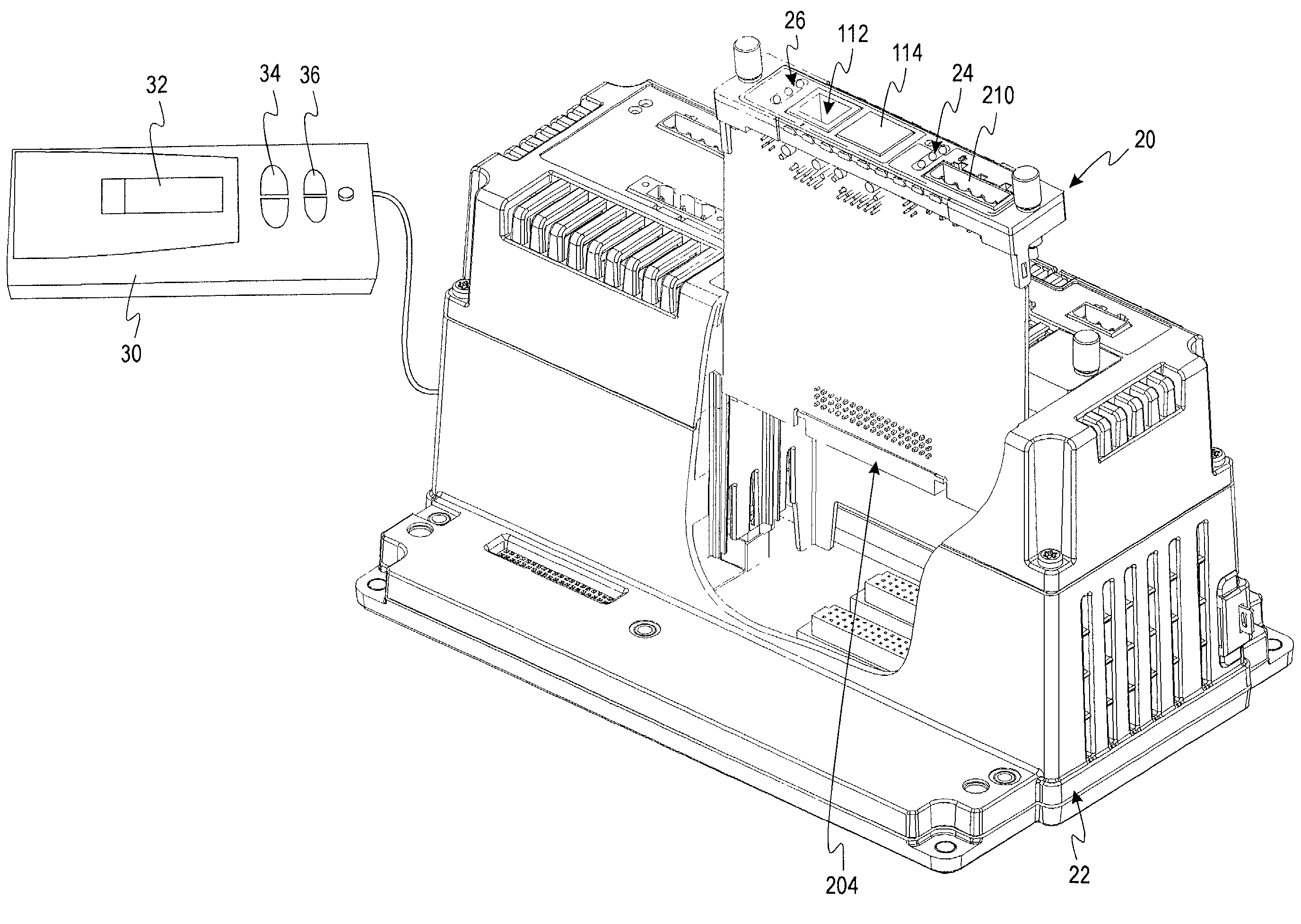
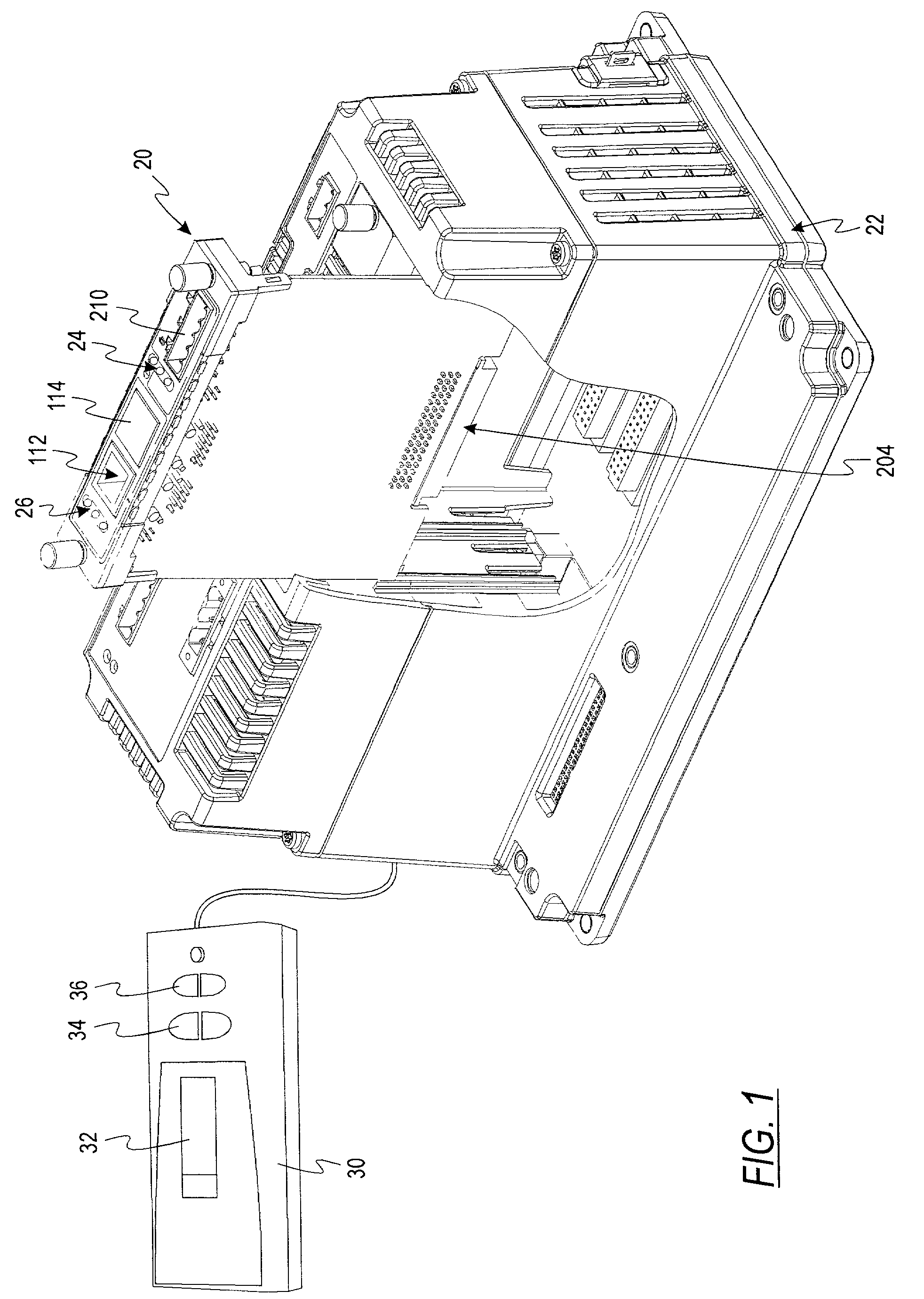
[0014]Referring now to the drawings, and initially to FIG. 1, in accordance with one embodiment of the invention, an Ethernet communications device comprises a Circuit Monitor 3000 / 4000 series Ethernet Communications Card (ECC) 20 is an installable option card, which can be utilized by the Square D CM3000 / 4000 series of meters (CM) 22. This option card will allow the meters to be accessed over Ethernet media and provide a Gateway function by allowing Ethernet access to other Square D PowerLogic compatible Modbus, Jbus, and / or SyMax slave RS485 devices.

[0015]The ECC provides a fast, direct Ethernet communication connection for the Series 4000 Circuit Monitor and allow Ethernet gateway functionality to a wide variety of POWERLOGIC-compatible MODBUS, JBUS, and / or SY / MAX devices. A typical application example is shown in FIG. 3.

[0016]The ECC allows access to custom HTML pages (stored in the circuit monitor) via a standard web browser. The pages are best viewed using Internet Explorer ve...


PUM


Abstract

An Ethernet communications system for a power monitoring system includes an Ethernet communications device having a processor, a communications interface capable of gathering, under control of the processor, real-time information from one or more slave devices. The processor and communications interface are operative for presenting the real-time information in a format useable by Hypertext Markup Language (HTML) pages.

Description

BACKGROUND OF THE INVENTION[0001]This invention is directed generally to the power monitoring arts, and more particularly, to an Ethernet communication system for use with a power monitoring device.[0002]While the invention may find other uses, the embodiment described herein is configured for use with a POWERLOGIC® power monitoring and control system which combines microprocessor-based instrumentation and control with internet software to provide information from an electrical distribution system. The system has such capabilities as alarm reporting, automatic control, high-accuracy instrumentation, power quality and disturbance monitoring and data sharing.[0003]Heretofore, the communications for this POWERLOGIC system were provided by an Ethernet gateway device, which was a stand-alone device capable of communicating through an RS485 daisy chain with one or more power monitoring and / or control devices. The Ethernet gateway device (EGW) did not include a Hyptertext transfer protocol...

Claims


Application Information

Patent Timeline
Patent Type & Authority Patents(United States)
IPC IPC(8): G06F15/173H04L29/06H04L29/08
CPCH04L29/06H04L67/06H04L67/34H04L69/16H04L67/02H04L69/163H04L69/165H04L9/40
Inventor CURRAY, TIMOTHY G.LAZENBY, BRADLEY A.
Owner SQUARE D CO
Why Eureka
Try Eureka