Centrally located ignition source in a combustion chamber

a central location and ignition source technology, applied in spark plugs, machines/engines, mechanical equipment, etc., can solve the problems of less than optimum ignition and combustion of air/fuel mixture within the combustion chamber, less than optimum efficiency, and increase in emissions

Active Publication Date: 2008-11-11
ENGINUITY POWER SYST INC
View PDF12 Cites 11 Cited by
  • Summary
  • Abstract
  • Description
  • Claims
  • Application Information

AI Technical Summary

Problems solved by technology

However, this generally results in less than optimum ignition and burning of the air / fuel mixture within the combustion chamber, due to the peripheral location of the ignition source in comparison to the central volume of the combustion chamber.
The peripheral location of the ignition source generally necessitates a richer fuel mixture due to the displaced position of the ignition source from its optimal center position, as well as resulting in increases in emissions and less than optimum efficiency, i.e., poorer fuel mileage than the ideal in a motor vehicle.

Method used


Image

  • Centrally located ignition source in a combustion chamber
  • Centrally located ignition source in a combustion chamber
  • Centrally located ignition source in a combustion chamber

Examples


Embodiment Construction

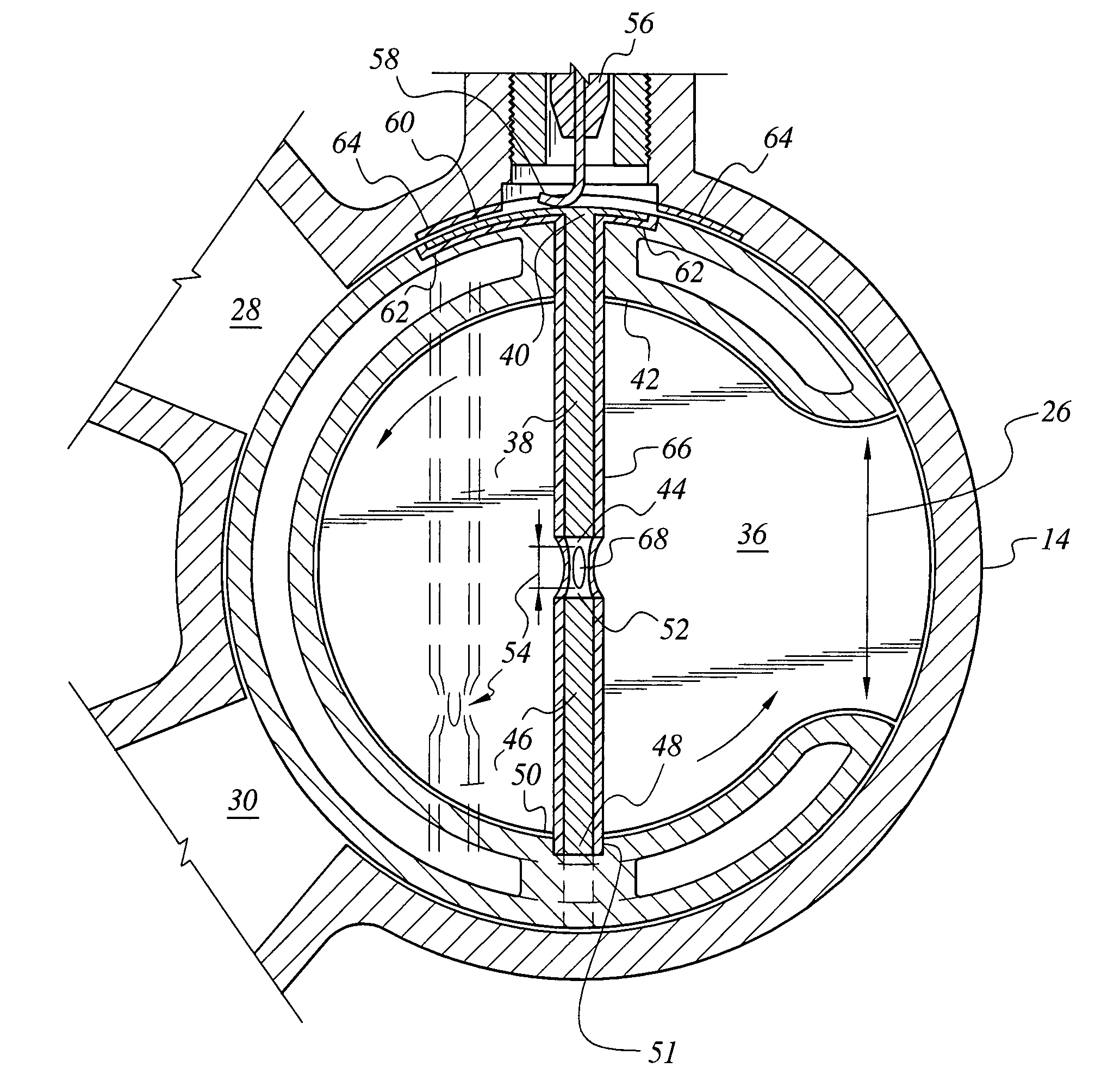
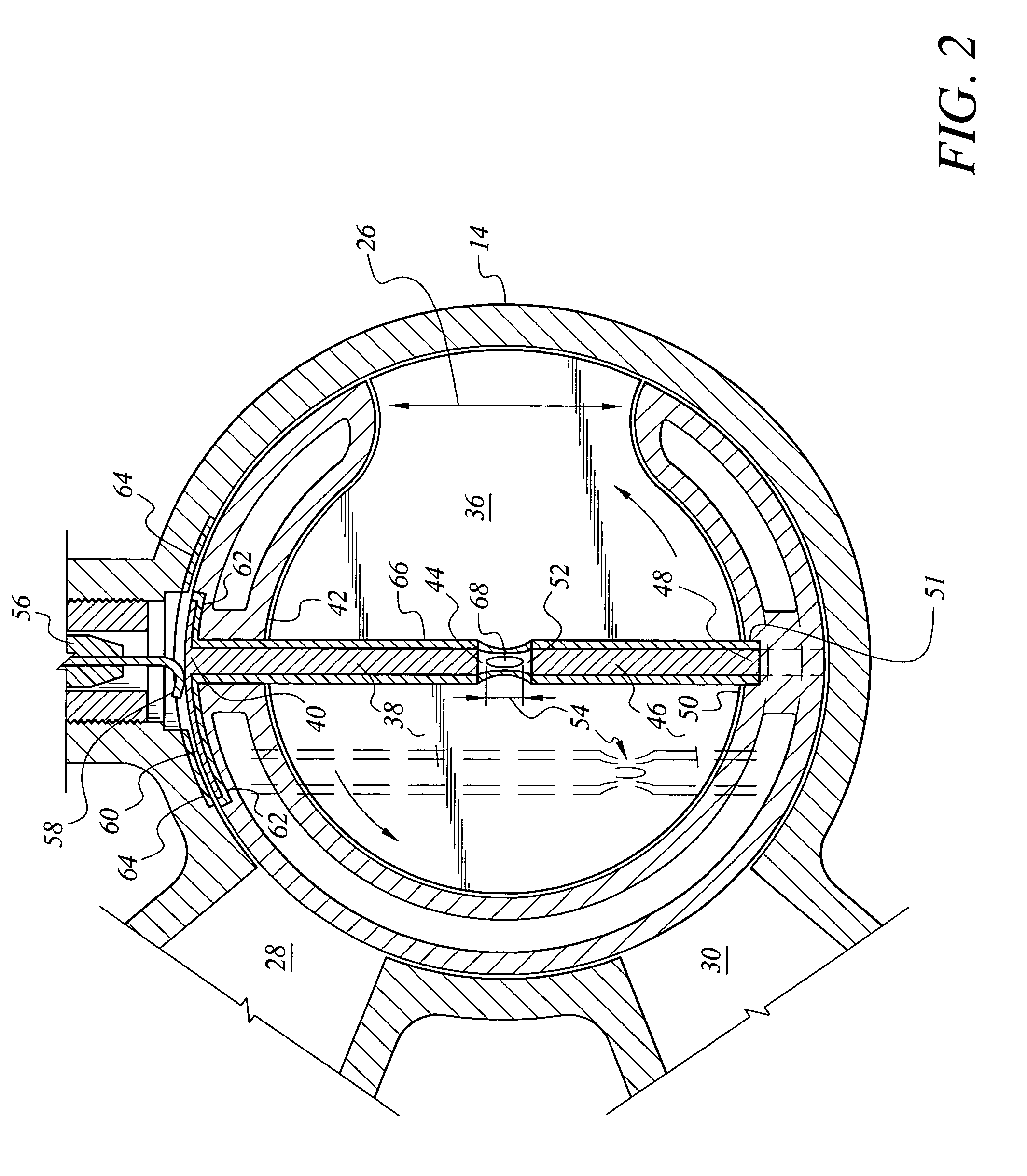
[0018]The present invention comprises various embodiments of an ignition source that provides a generally centrally located ignition point within a combustion chamber. The combustion chamber may be any practicable volume as used in furnaces, internal combustion engines, etc., but the present invention is particularly directed to incorporation with an opposed piston engine, i.e., an engine having a central combustion chamber located between each opposed piston pair, with each piston driving an outboard crankshaft. The present ignition source is adapted for inclusion in such an engine where the engine incorporates a rotary sleeve valve, which defines the generally cylindrical wall of the combustion chamber, with the ignition source rotating with the sleeve valve during engine operation.

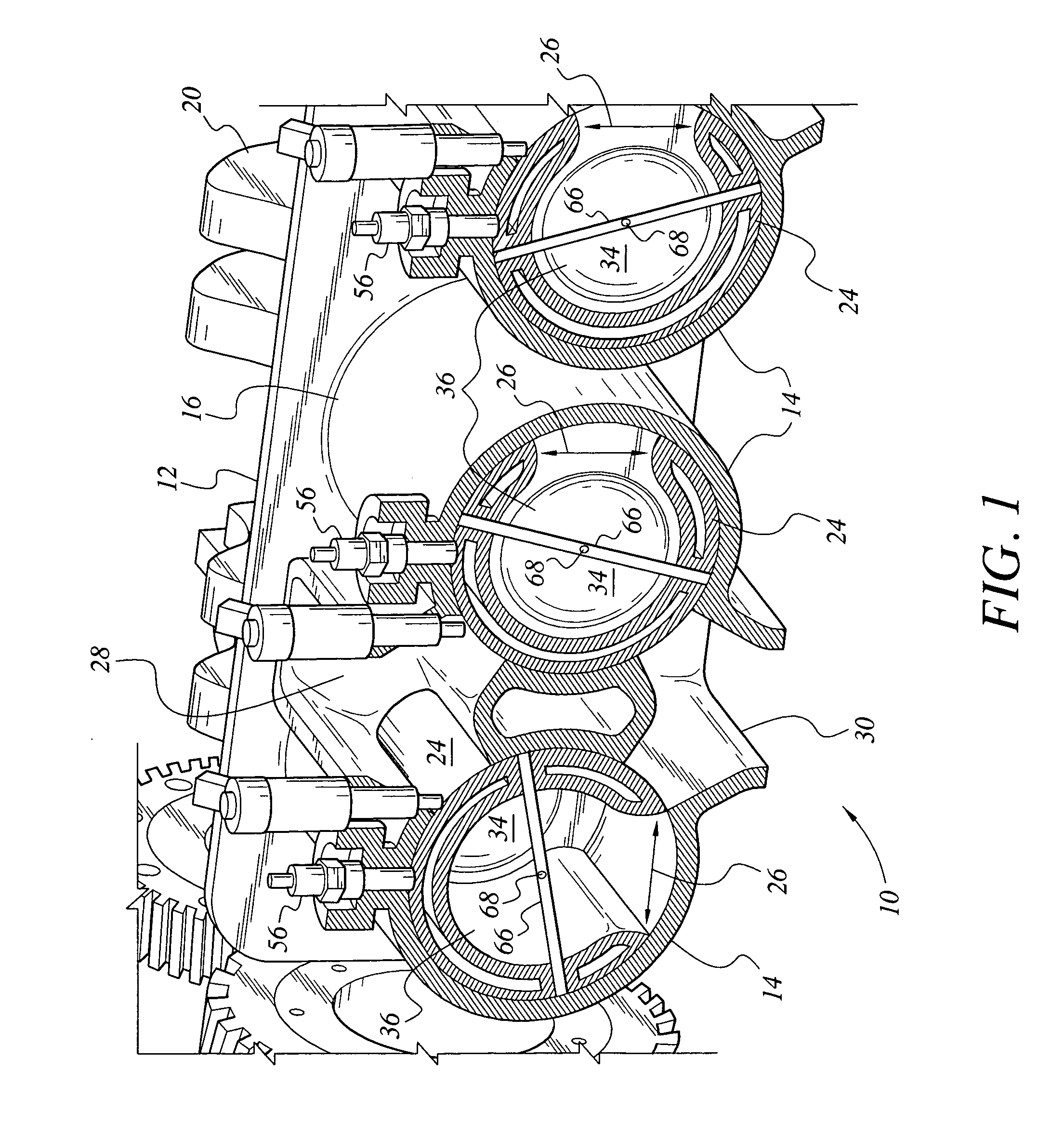
[0019]FIG. 1 of the drawings provides a section view through the center of an opposed piston engine 10, the view being drawn through the center of the combustion chambers of the engine. The complete eng...


PUM


Abstract

The centrally located ignition source in a combustion chamber is an electrical conductor spanning the general center of the combustion chamber, with a spark gap at the general center of the conductor. The device may be offset from the combustion chamber centerline, and / or the spark gap may be offset from the conductor center, as required. The centrally located ignition source is particularly well suited for use in an opposed piston engine having a rotary sleeve valve mechanism, with the conductor rotating with the sleeve valve and crossing the combustion chamber between the two pistons. An arcuate commutator section may be disposed upon the exterior of the rotary sleeve valve, with a contact finger making electrical contact between the electrical energy source and the commutator section to supply electrical energy to the ignition source. The device is also suitable for use in stationary installations, e.g., gas furnace combustors, etc.

Description

CROSS-REFERENCE TO RELATED APPLICATION[0001]This application claims the benefit of U.S. Provisional Patent Application Ser. No. 60 / 731,266, filed Oct. 31, 2005.BACKGROUND OF THE INVENTION[0002]1. Field of the Invention[0003]The present invention relates generally to spark ignition systems for use in combustion devices, e.g., reciprocating engines, furnaces, etc. More specifically, the present invention comprises various embodiments of an ignition device that spans a combustion chamber volume, with the ignition spark occurring in the general center of the combustion chamber volume.[0004]2. Description of the Related Art[0005]Electrical or spark ignition systems for various types of combustion devices are extremely well known. Such spark ignition systems are commonly used to ignite the fuel / air mixture in reciprocating engines, as well as other types of engines. Such spark ignition systems are also used in heater combustors, furnaces, and various other devices that burn fuel to produc...

Claims


Application Information

Patent Timeline
Patent Type & Authority Patents(United States)
IPC IPC(8): F02P15/00F02B57/00
CPCF02B75/282F02P15/001
Inventor WARREN, JAMES C.
Owner ENGINUITY POWER SYST INC
Why Eureka
Try Eureka