
Controller of internal combustion engine
a controller and internal combustion engine technology, applied in electrical control, automatic ignition control, force/torque/work measurement apparatus, etc., can solve problems such as deviation in air-fuel ratio, deterioration of startability or exhaust emission, and correct fuel correction, so as to improve the startability of the engine, the effect of accurate control and smooth starting
- Summary
- Abstract
- Description
- Claims
- Application Information
AI Technical Summary
Benefits of technology
Problems solved by technology
Method used
Image

Examples
Embodiment Construction
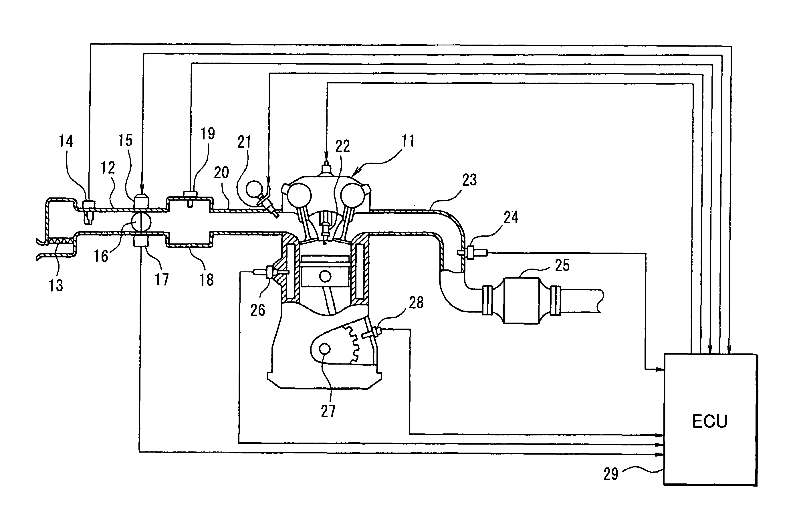
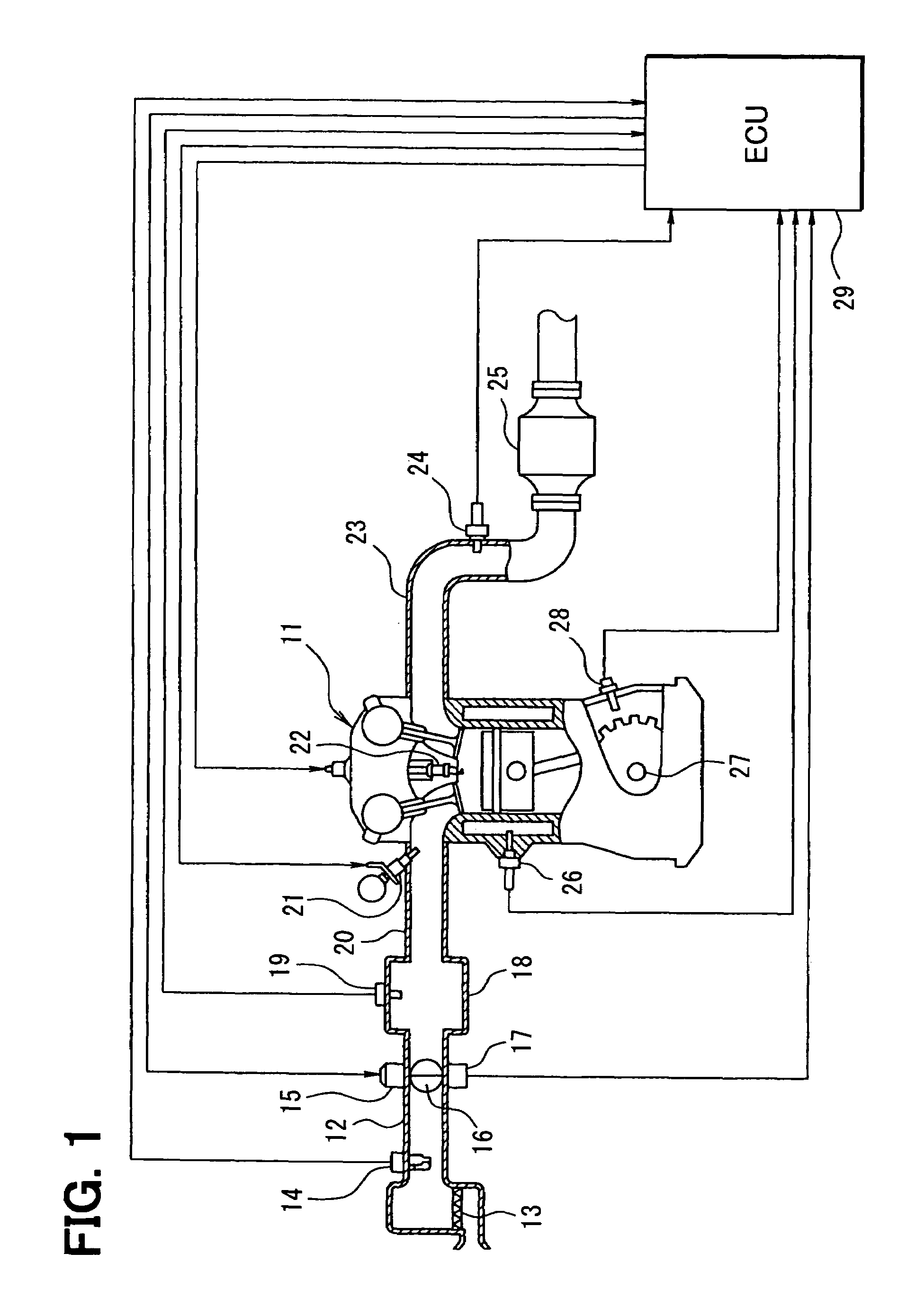
[0034]Referring to FIG. 1, an engine control system according to a first example embodiment of the present invention is illustrated. An air cleaner 13 is provided at the upstream-most portion of an intake pipe 12 of an internal combustion engine 11. An airflow meter 14 for sensing an air intake amount is provided downstream of the air cleaner 13. A throttle valve 16, an opening degree (throttle opening degree) of which is regulated by a motor 15, and a throttle opening degree sensor 17 for sensing the opening degree of the throttle valve 16 are provided downstream of the airflow meter 14.
[0035]A surge tank 18 is provided downstream of the throttle valve 16. An intake pipe pressure sensor 19 for sensing intake pipe pressure is provided in the surge tank 18. The surge tank 18 is provided with an intake manifold 20 for introducing the air into respective cylinders of the engine 11. Fuel injection valves 21 for injecting the fuel are attached near intake ports of the intake manifold 20 ...
PUM
 Abstract
Description
Claims
Application Information