Hydraulic damping force control unit, hydraulic shock absorber, front fork for vehicle, and hydraulic rotary damper

a technology of hydraulic shock absorber and control unit, which is applied in the direction of shock absorbers, vibration dampers, springs/dampers, etc., can solve the problems of unfavorable opening of thedamping force control valve, insufficient time for the valve element to be closed, and large differential pressure, etc., to achieve high hydraulic pressure, suitable damping force, and constant and suitable damping force

Inactive Publication Date: 2008-11-11
YAMAHA MOTOR CO LTD
View PDF14 Cites 23 Cited by
  • Summary
  • Abstract
  • Description
  • Claims
  • Application Information

AI Technical Summary

Benefits of technology

[0026]Thus, according to the damping force control unit of the present invention, the relatively high hydraulic pressure can be utilized to keep the poppet valve closed while it is on standby. Consequently, the poppet valve, for example, connected to a hydraulic cylinder, can generate suitable damping force right from the moment when the hydraulic cylinder has shifted from the compression stroke to the expansion stroke or vice versa.
[0027]The poppet valve of a pressure control unit that is on standby can be kept closed when the piston starts to move after passing over dead center, for example, when the hydraulic cylinder shifts from the compression stroke to the expansion stroke or vice versa. Thus, it is possible to provide a hydraulic shock absorber which generates constant and suitable damping force.
[0028]When the hydraulic shock absorber is expanded, the poppet valve of the damping force control unit that is connected to the head side fluid chamber is on standby as closed, and when the hydraulic shock absorber is compressed, the poppet valve of the damping force control unit that is connected to the rod side fluid chamber is on standby as closed. Therefore, the poppet valve of a pressure control unit that is on standby can be kept closed when the piston starts to move after passing over dead center, for example, when the hydraulic cylinder of the hydraulic shock absorber shifts from the compression stroke to the expansion stroke or vice versa. Thus, it is possible to provide a front fork which generates constant and suitable damping force.
[0029]Additionally, in the front fork of this invention, since one of the paired left and right hydraulic shock absorbers generates damping force in the compression stroke, and the other shock absorber generates damping force in the expansion stroke, damping force can be generated in both the compression stroke and the expansion stroke, using the two hydraulic cylinders and the two damping force control units. Thus, the size of pistons and rods can be selected independently between the hydraulic shock absorber, which generates damping force in the compression stroke and the hydraulic shock absorber, which generates damping force in the expansion stroke. This produces an additional effect that the degree of freedom in setting the maximum damping force and the maximum working pressure is increased.
[0030]When the movable partition wall is moved from the one fluid chamber side toward the other fluid chamber side, the poppet valve of the damping force control unit that is connected to the one fluid chamber is on standby as closed, and when the movable partition wall is moved from the other fluid chamber side toward the one fluid chamber side, the poppet valve of the damping force control unit that is connected to the other fluid chamber is on standby as closed. Therefore, the poppet valve of a pressure control unit that is on standby can be closed when the moving direction of the movable partition wall of the rotary damper is changed. Thus, it is possible to provide a rotary damper, which generates constant and suitable damping force.

Problems solved by technology

In other words, when the hydraulic shock absorber is in the expansion stroke, the damping force control valve that should be on standby as closed is unfavorably opened.
When the frequency and amplitude of vibration of a wheel are relatively large, however, the flow rate of pressurized fluid through the head side check valve is high and hence the differential pressure is large.
Thus, occasionally, there is not enough time for the valve element to be closed before the piston of the hydraulic shock absorber reaches dead center in the expansion stroke and the valve is kept opened even after the hydraulic shock absorber has shifted to a compression stroke.
If the compression side damping force control valve is opened when the hydraulic shock absorber has shifted from the expansion stroke to the compression stroke as described above, the compression side damping force control valve cannot generate a magnitude of damping force necessary at the moment.
In other words, the damping force to be generated by the compression side damping force control valve at this time is unstable (the damping force waveform is disordered.
On the contrary, when the hydraulic shock absorber shifts from the compression stroke to the expansion stroke, the expansion side damping force control valve is on standby as opened, which causes the same problem as described above.
Also, because the expansion side damping force control valve, which should be closed, is opened when the hydraulic shock absorber has shifted from the compression stroke to the expansion stroke, the damping force is unstable in the range indicated by symbol b in FIG. 11.

Method used


Image

  • Hydraulic damping force control unit, hydraulic shock absorber, front fork for vehicle, and hydraulic rotary damper
  • Hydraulic damping force control unit, hydraulic shock absorber, front fork for vehicle, and hydraulic rotary damper
  • Hydraulic damping force control unit, hydraulic shock absorber, front fork for vehicle, and hydraulic rotary damper

Examples


first embodiment

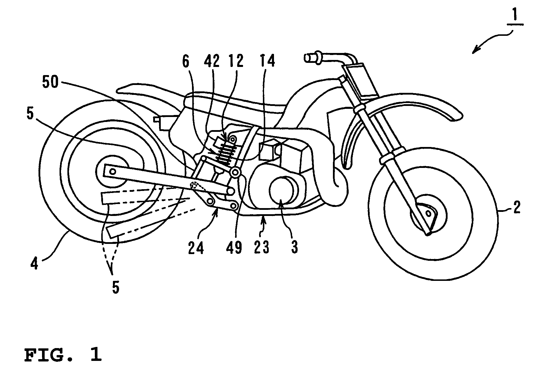
[0044]An embodiment of a hydraulic damping force control unit according to the present invention will be hereinafter described in detail with reference to FIGS. 1 through 3. The description will be based on an example where the hydraulic damping force control unit according to the present invention is applied to a rear cushion unit of a motorcycle.

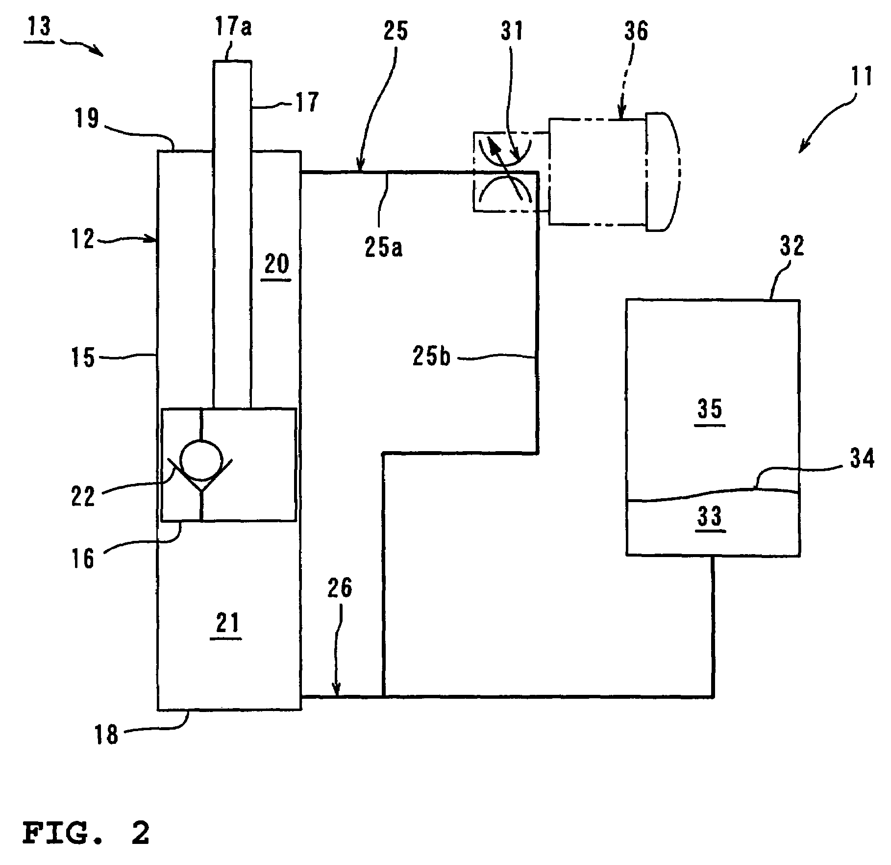
[0045]FIG. 1 is a side view of a motorcycle having a hydraulic damping force control unit according to the present invention. FIG. 2 is a diagram showing the construction of the hydraulic damping force control unit according to the present invention. FIG. 3 is a sectional view of a damping force control valve. FIG. 4 is a block diagram showing the construction of the hydraulic damping force control unit according to the present invention.

[0046]In the drawings, reference numeral 1 denotes a motorcycle according to this embodiment. Reference numeral 2 denotes a front wheel, 3 an engine, 4 a rear wheel, 5 a rear arm, and 6 a rear cushion unit...

second embodiment

[0079]Aside from the foregoing exemplary embodiment where damping force is generated only when the hydraulic shock absorber is in the expansion stroke, another construction is possible where damping force is generated also in the compression stroke. An exemplary embodiment with such a construction will be described in detail with reference to FIGS. 5 through 7.

[0080]FIG. 5 is a diagram showing the construction of a hydraulic shock absorber having two damping force control valves connected to a single hydraulic cylinder. FIG. 6 is a block diagram showing the construction of a control system with the two damping force control valves. FIG. 7 is a graph showing the operation of the hydraulic shock absorber and the damping force control valves. In the drawings, components identical or equivalent to those described in relation to FIGS. 1 to 4 are denoted by the same reference numerals, and their detailed descriptions will not be repeated as appropriate.

[0081]As shown in FIG. 5, the hydrau...

third embodiment

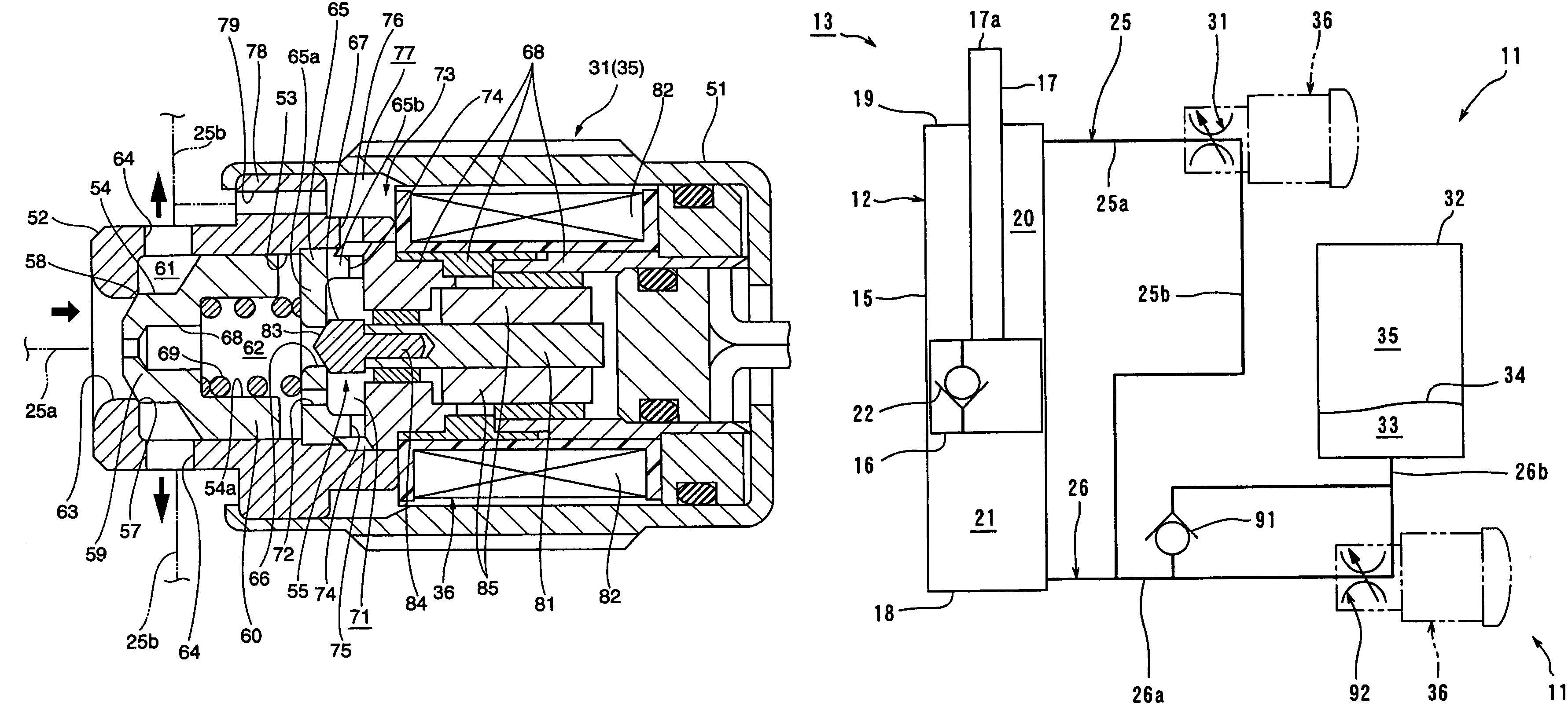
[0089]The pressure conduction path 72 of the expansion side damping force control valve 31 and the compression side damping force control valve 92 can be provided in the pilot valve 55 as shown in FIG. 8.

[0090]FIG. 8 is a sectional view of another embodiment of the damping force control valve. In the drawing, components identical or equivalent to those described in relation to FIGS. 1 to 7 are denoted by the same reference numerals, and their detailed descriptions will not be repeated as appropriate.

[0091]As shown in FIG. 8, the valve element 67 of the pilot valve 55 is formed with pressure conduction paths 72, which are notches or cutouts provided in portions of the tapered surface 83, which contact the opening edge of the through hole 66. A plurality of the pressure conduction paths 72 are provided at intervals around the circumference of the valve element 67.

[0092]In one aspect, such a construction with the pressure conduction paths 72 provided in the valve element 67 also produc...


PUM


Abstract

A damping force is generated by keeping a damping force control valve closed when a piston of a hydraulic shock absorber starts to move from compression side dead center or expansion side dead center. A damping force control valve including a poppet valve for opening and closing a first fluid path is provided. A pilot pressure chamber defined from the fluid path by a valve element of the damping force control valve is provided. A linear solenoid and a pilot valve for increasing and reducing the hydraulic pressure in the pilot pressure chamber are provided. A check valve disposed in parallel with the damping force control valve is provided in a piston. A communication path for communication between the first fluid path downstream of the damping force control valve and the pilot pressure chamber is provided.

Description

BACKGROUND OF THE INVENTION[0001]1. Field of the Invention[0002]The present invention relates to a hydraulic damping force control unit, a hydraulic shock absorber, a front fork for a vehicle, and a hydraulic rotary damper which use a poppet valve to generate damping force.[0003]2. Description of Related Art[0004]One example of conventional hydraulic shock absorber having a damping force control valve is disclosed in Japanese Patent Document JP-B-3306526. The hydraulic shock absorber disclosed in JP-B-3306526 is for use in suspension systems of vehicles, and constructed with a hydraulic cylinder provided between the wheel side and the vehicle body frame side, damping force control valves provided in a hydraulic circuit of the hydraulic cylinder, and so forth.[0005]The hydraulic cylinder is constructed with a cylinder body filled with hydraulic fluid, a piston which defines the inside of the cylinder body into a head side fluid chamber and a rod side fluid chamber, and so forth. The ...

Claims


Application Information

Patent Timeline
Patent Type & Authority Patents(United States)
IPC IPC(8): F16F9/46
CPCF16F9/465
Inventor FUKUDA, HIROMINAKANOSONO, HARUHIKO
Owner YAMAHA MOTOR CO LTD
Why Eureka
Try Eureka